
Car Air Conditioning Schematic Diagram
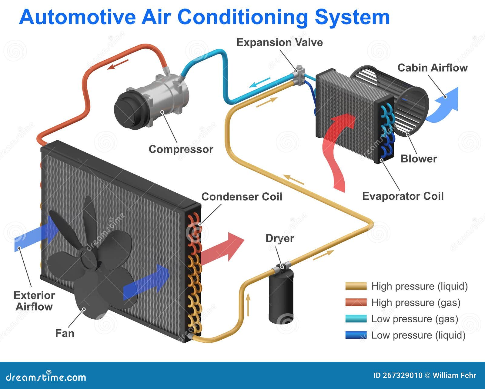
Welcome, fellow gearheads! Today, we're diving deep into a critical system of modern vehicles: the air conditioning system. Specifically, we’ll be dissecting the schematic diagram of your car's A/C. This isn’t just some fancy blueprint; it’s your roadmap to understanding, troubleshooting, and potentially even repairing this complex system. Think of it as your electrical and mechanical decoder ring for all things cool!
Purpose: Why Bother with the A/C Schematic Diagram?
Why should you, an experienced DIYer, even care about an A/C schematic? Simple: because it empowers you. Understanding the schematic allows you to:
- Diagnose problems efficiently: Forget randomly swapping parts. The schematic guides you to the *source* of the issue.
- Perform targeted repairs: Knowing the flow of refrigerant and electricity allows for precise interventions.
- Understand system operation: Gain a deeper appreciation of how the A/C components interact.
- Customize your system (carefully!): While not for the faint of heart, the schematic can inform modifications, such as upgrading components or adding auxiliary systems (with proper knowledge and precautions, of course).
- Save money: Avoid unnecessary trips to the mechanic by diagnosing and fixing problems yourself.
- Learn: The A/C system is an excellent example of how thermal, electrical, and mechanical systems interact.
Key Specs and Main Parts of the A/C System
Before we jump into the schematic itself, let's quickly review the major components and their roles:
- Compressor: The heart of the system. Driven by the engine via a belt, it compresses the refrigerant gas, raising its temperature and pressure.
- Condenser: Located at the front of the car, the condenser dissipates heat from the high-pressure, high-temperature refrigerant gas, causing it to condense into a high-pressure liquid.
- Receiver-Drier/Accumulator: This component filters debris and absorbs moisture from the refrigerant. In systems with a thermal expansion valve (TXV), it's called a receiver-drier and is located on the high-pressure side. In systems with an orifice tube, it's called an accumulator and is located on the low-pressure side.
- Expansion Valve/Orifice Tube: These components control the flow of high-pressure liquid refrigerant into the evaporator. They also reduce the pressure of the refrigerant, causing it to rapidly expand and cool. The thermal expansion valve (TXV) is a more sophisticated control device that meters refrigerant flow based on evaporator temperature.
- Evaporator: Located inside the car's dashboard, the evaporator is where the cold magic happens. The low-pressure liquid refrigerant absorbs heat from the air blowing across it, cooling the air that enters the cabin.
- Refrigerant Lines: These tubes and hoses carry the refrigerant between the components. High-side lines carry high-pressure refrigerant; low-side lines carry low-pressure refrigerant.
- A/C Clutch: An electromagnetic clutch that engages and disengages the compressor from the engine.
- Pressure Switches: Protect the system by monitoring refrigerant pressure. They can shut off the compressor if the pressure is too high or too low.
- Blower Motor: Forces air across the evaporator.
- Control System: Includes the A/C controls on your dashboard, sensors, and potentially a control module that manages the A/C system's operation.
Key Specs: When troubleshooting, you'll need to know things like refrigerant type (e.g., R-134a, R-1234yf), system pressures (high and low side), and voltage/resistance values for electrical components. These are usually found in your vehicle's service manual.
Understanding Schematic Symbols
The schematic is a symbolic representation of the A/C system. Learning to "read" it is crucial. Here are some common symbols:
- Lines: Solid lines typically represent refrigerant lines. Dotted or dashed lines often represent electrical wiring. Line thickness may indicate the size/capacity of the line or wire.
- Arrows: Indicate the direction of refrigerant flow.
- Circles: Can represent various components, depending on what's inside the circle. Look for labels or other adjacent symbols to identify them.
- Squares/Rectangles: Often represent electrical components like relays, switches, or control modules.
- Resistor Symbol (zig-zag line): Represents a resistor, used to limit current flow in electrical circuits.
- Capacitor Symbol (two parallel lines): Represents a capacitor, used to store electrical energy.
- Diode Symbol (triangle pointing to a line): Represents a diode, allowing current to flow in only one direction.
- Ground Symbol: Indicates a connection to the vehicle's chassis ground.
Colors: Wire colors are often indicated on the schematic (e.g., BLU for blue, RED for red, GRN for green). Knowing the wire color helps you locate the correct wire in the vehicle's wiring harness.
Important: Always refer to the specific schematic for your vehicle's make, model, and year. Symbols and conventions can vary. A service manual is your best friend!
How the A/C System Works (According to the Schematic)
The schematic shows the entire A/C loop. Starting with the compressor, you'll see how the refrigerant is compressed and sent to the condenser. The schematic will illustrate the high-pressure side of the system in contrast with the low-pressure side. You'll be able to trace the refrigerant's path through the receiver-drier/accumulator and the expansion valve/orifice tube, and then into the evaporator. Finally, the low-pressure refrigerant returns to the compressor to repeat the cycle. Electrically, the schematic shows how the A/C clutch is engaged, often involving relays, pressure switches, and the A/C control module.
A Simplified Flow:
- The A/C request is made by the driver.
- The control system checks various parameters (engine temperature, refrigerant pressure) to determine if the A/C can be safely activated.
- If conditions are favorable, the control system energizes the A/C clutch relay.
- The relay sends power to the A/C clutch, engaging the compressor.
- The compressor circulates refrigerant through the system, causing cooling.
- Pressure switches monitor refrigerant pressure, shutting off the compressor if pressure is too high or too low.
Real-World Use: Basic Troubleshooting
Let's say your A/C isn't blowing cold. Here's how the schematic can help:
- Check the A/C clutch: The schematic shows the wiring to the A/C clutch. Use a multimeter to check for voltage at the clutch connector when the A/C is turned on. No voltage? Trace the wiring back to the relay and pressure switches.
- Inspect pressure switches: Locate the pressure switches on the schematic. Use a multimeter to check for continuity through the switches. An open circuit indicates a faulty switch or an out-of-range refrigerant pressure.
- Verify relay operation: Locate the A/C clutch relay on the schematic. Check for voltage at the relay coil and output terminals. You can also try swapping the relay with a known good one to see if that fixes the problem.
Example: If the schematic shows a high-pressure switch in series with the A/C clutch relay coil, and the A/C isn't working, you'd suspect either a faulty high-pressure switch or excessively high refrigerant pressure. Checking the switch with a multimeter will confirm its functionality. You would then need to consult pressure readings to determine proper system charge.
Safety First!
Working on A/C systems can be dangerous. Consider these safety precautions:
- Refrigerant: Refrigerant can cause frostbite and is harmful if inhaled. Never release refrigerant into the atmosphere. Have it properly recovered by a qualified technician.
- High Pressure: The high-pressure side of the system contains refrigerant at very high pressure. Never disconnect lines or components without first evacuating the system using appropriate equipment.
- Electrical: Disconnect the negative battery cable before working on any electrical components.
- Tools: Use proper A/C service tools, including manifold gauges, vacuum pump, and refrigerant recovery machine.
- Knowledge: Don't attempt repairs beyond your skill level. Consult a qualified technician if you're unsure.
High-Risk Components: The compressor and the high-pressure lines are particularly risky due to the high pressures involved. Electrical components related to the A/C clutch and blower motor can also pose a shock hazard if not handled carefully.
We've covered a lot of ground, and the schematic diagram is a valuable tool in your DIY arsenal. Armed with this knowledge, you can approach A/C troubleshooting with confidence and precision.
We have the file you need to download so that you can diagnose your vehicle's A/C: Car Air Conditioning Schematic Diagram.