Car Aircon Compressor Wiring Diagram
Alright, let's dive into the fascinating world of automotive air conditioning compressor wiring diagrams. This isn't just some abstract schematic; it's your roadmap to understanding, diagnosing, and potentially repairing one of the most crucial (and often overlooked) systems in your car – the air conditioning. Whether you're facing a sweltering summer commute or simply want to deepen your understanding of automotive tech, grasping the compressor wiring is essential. We’re assuming you have some basic electrical knowledge and know your way around a multimeter. This guide will help you translate those skills to the A/C system.
Purpose: Why Bother with the Diagram?
Why bother decoding these complex lines and symbols? Several reasons:
- Troubleshooting: When your A/C blows warm air, the diagram allows you to systematically trace the electrical path, pinpointing faults like blown fuses, faulty relays, or wiring breaks.
- Repair: Once you've identified the problem, the diagram guides your repair efforts, ensuring you replace the correct components and reconnect wiring correctly.
- Modification and Upgrades: Thinking of retrofitting an A/C system into a classic car? Or perhaps upgrading to a more efficient compressor? The wiring diagram is indispensable for these projects.
- Learning: Even if you don't plan on tackling A/C repairs yourself, understanding the system's electrical architecture gives you a deeper appreciation for automotive technology. It also equips you to better communicate with your mechanic.
Key Specs and Main Parts in the Circuit
Before we decipher the diagram, let's define the key players and their roles:
- Compressor: The heart of the A/C system, the compressor pumps refrigerant, increasing its pressure and temperature. Electrically, it's activated by a clutch engaging when power is applied.
- Compressor Clutch: An electromagnetic clutch that engages the compressor when energized, driven by a pulley connected to the engine's accessory belt. This is typically a 12V DC circuit.
- Pressure Switches: Critical safety devices that monitor refrigerant pressure.
- Low-Pressure Switch: Prevents the compressor from running when refrigerant levels are too low, protecting it from damage.
- High-Pressure Switch: Shuts down the compressor if refrigerant pressure becomes excessively high, preventing system damage or rupture.
- A/C Relay: An electromechanical switch that controls the power supply to the compressor clutch. It's triggered by the A/C request signal.
- Fuse: A safety device that protects the circuit from overcurrent. A blown fuse indicates a problem elsewhere in the circuit.
- Thermistor/Temperature Sensor: Monitors the evaporator core temperature to prevent freezing. This is often integrated into the control system.
- Control Module (HVAC): The brain of the system, receiving inputs from various sensors and switches, and controlling the A/C compressor, blower motor, and other components. Sometimes this is a dedicated module, other times integrated into the main ECU.
Decoding the Symbols: Lines, Colors, and Icons
Wiring diagrams use a standardized set of symbols to represent components and connections. Let's break down the key elements:
- Lines: Solid lines represent wires, indicating the electrical path. Dashed lines might represent signal or communication lines.
- Colors: Wire colors are crucial for identification. Common colors include red (power), black (ground), blue, green, yellow, and white. The diagram *should* provide a color code legend. Remember that color codes can vary between manufacturers and even models within the same manufacturer.
- Icons:
- Coils: Represent relays or solenoids.
- Rectangles: Represent switches, sensors, or electronic modules.
- Circles: Often represent grounds or connection points.
- Fuses: Typically depicted as a zig-zag line enclosed in a rectangle.
- Resistors: Zig-zag lines.
- Capacitors: Two parallel vertical lines.
- Diodes: Triangle with a line at the point. The line indicates the direction of current flow.
- Wire Gauge: Some diagrams might include wire gauge information (e.g., 16 AWG). This is crucial for selecting replacement wire.
- Connector Numbers: Wires connected at a specific connector will be labeled with the connector number, and often a pin number within the connector. This is invaluable for pinpointing connection issues.
Important Note: Always refer to the specific wiring diagram for your vehicle's make, model, and year. Generic diagrams can be helpful for understanding the basic principles, but they won't account for the nuances of your particular system.
How the A/C Compressor Circuit Works
Here's a simplified overview of how the A/C compressor circuit typically functions:
- A/C Request: The driver activates the A/C system, typically by pressing an A/C button on the dashboard.
- Control Module Activation: The HVAC control module receives this request and evaluates other inputs, such as the engine temperature, ambient temperature, and pressure switch status.
- Relay Control: If all conditions are met, the control module energizes the A/C relay.
- Power to Clutch: The energized relay closes, providing 12V power to the A/C compressor clutch.
- Compressor Engagement: The clutch engages, connecting the compressor to the engine's accessory belt, initiating refrigerant compression.
- Pressure Monitoring: The pressure switches continuously monitor refrigerant pressure. If the pressure falls outside the acceptable range (too low or too high), the switches signal the control module to de-energize the relay, disengaging the compressor clutch and preventing damage.
- Temperature Monitoring: The thermistor monitors the evaporator core temperature to prevent icing. If the temperature drops too low, the control module may cycle the compressor on and off to regulate temperature.
Real-World Use: Basic Troubleshooting Tips
Okay, your A/C is blowing warm. Where do you start with the wiring diagram?
- Check the Fuse: This is the first and easiest step. Use the diagram to locate the A/C compressor fuse and check for continuity with a multimeter. A blown fuse strongly suggests an overcurrent condition.
- Inspect the Relay: Locate the A/C relay using the diagram. You can test the relay itself by applying 12V to the coil terminals and checking for continuity across the switch terminals. You can also swap it with a known working relay of the same type.
- Verify Power to the Clutch: With the A/C on, use a multimeter to check for 12V at the A/C compressor clutch connector. If there's no power, trace the wiring back through the relay and pressure switches.
- Check the Pressure Switches: Use the diagram to identify the low- and high-pressure switches. Disconnect the connectors and check for continuity across the switch terminals when the system is supposed to be running. An open circuit indicates a faulty switch or incorrect refrigerant pressure.
- Inspect Wiring and Connectors: Visually inspect the wiring harness for any signs of damage, corrosion, or loose connections. Pay close attention to connectors, as these are common points of failure. Use the wiring diagram to identify the correct wires and connectors.
Example: Let's say your diagram shows that the power to the compressor clutch runs through a low-pressure switch. You check the switch and find it's open even with the system charged. That points to a faulty low-pressure switch.
Safety First! Handling High-Risk Components
Working with automotive electrical systems can be dangerous. Here are some crucial safety precautions:
- Disconnect the Battery: Before working on any electrical circuit, disconnect the negative battery terminal to prevent short circuits and electrical shocks.
- Use Proper Tools: Use insulated tools designed for automotive electrical work.
- Work in a Well-Ventilated Area: Some refrigerants can be harmful if inhaled.
- Discharge the A/C System (If Necessary): If you need to disconnect refrigerant lines, have the system professionally discharged to avoid releasing harmful refrigerant into the atmosphere.
- Don't Tamper with High-Voltage Components: Hybrid and electric vehicles have high-voltage A/C compressors. Do *not* attempt to repair these systems without proper training and equipment. The voltages involved are potentially lethal.
Important Reminder: If you are not comfortable working with electrical systems or handling refrigerant, it is always best to consult a qualified automotive technician.
By understanding the A/C compressor wiring diagram, you've armed yourself with valuable knowledge for troubleshooting, repairing, and even modifying your car's air conditioning system. Remember to always prioritize safety and consult the specific diagram for your vehicle. Good luck, and stay cool!
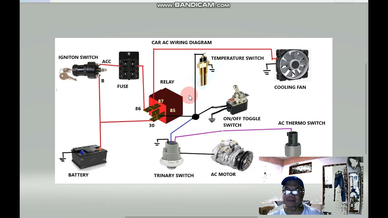
We have a generic, annotated A/C compressor wiring diagram available for download. This diagram can be a helpful reference alongside your specific vehicle's schematic. Contact us to request the file.