
Car Aircon Electrical Wiring Diagram
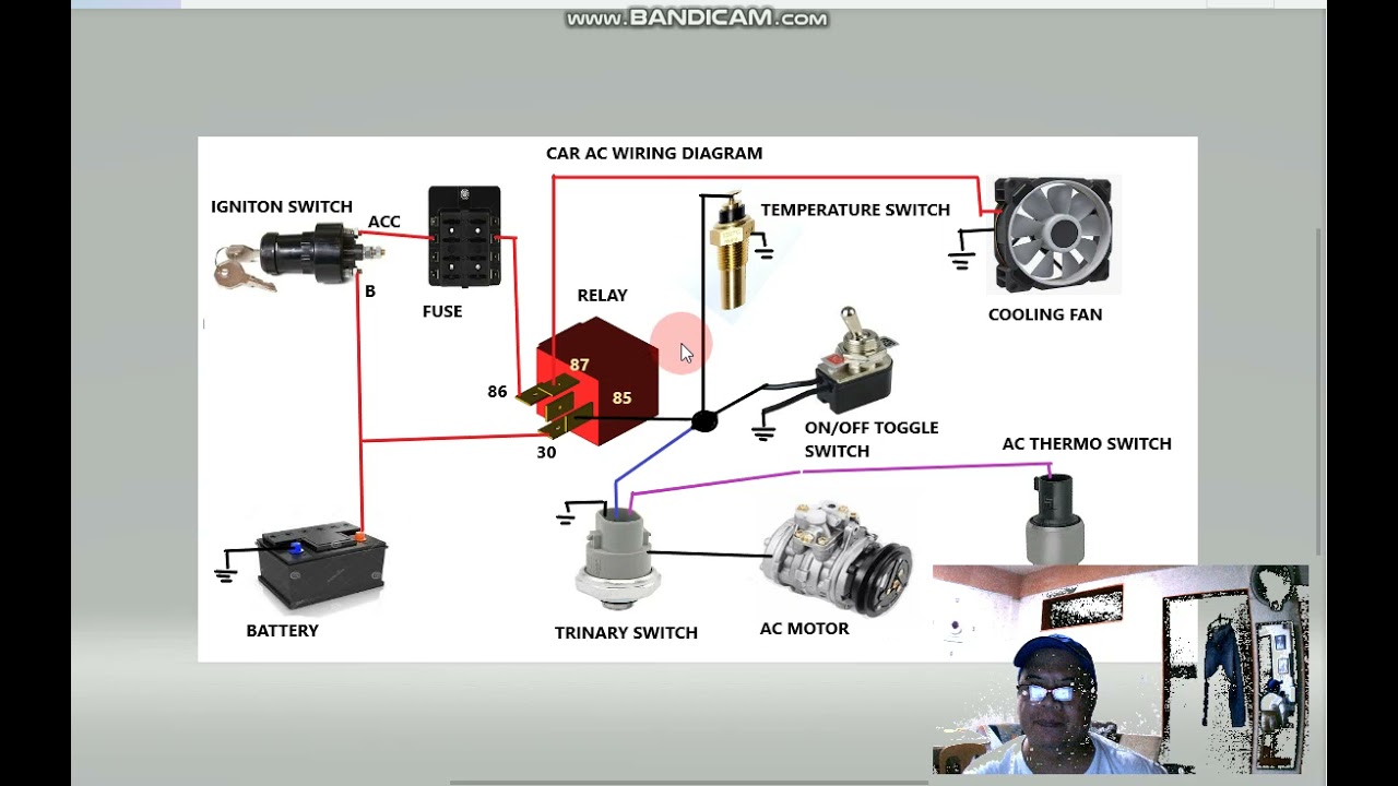
Alright, let's dive into the often-overlooked but crucial world of car air conditioning electrical wiring diagrams. Knowing how to read and understand these diagrams isn't just for professional mechanics; it’s an invaluable skill for any serious DIY car enthusiast, modder, or even a mechanically-minded car owner. Whether you're diagnosing a faulty compressor, installing an aftermarket A/C system, or simply trying to understand how your car's climate control works, this knowledge is power. We’re going to demystify these schematics, focusing on clarity and practical application.
Purpose of the A/C Electrical Wiring Diagram
The primary purpose of an A/C electrical wiring diagram is to provide a visual roadmap of the electrical circuits that control your car's air conditioning system. Think of it as a detailed instruction manual for the electrical heart of your A/C. Here's why understanding this diagram is so important:
- Troubleshooting and Diagnosis: When your A/C stops blowing cold air, a wiring diagram can help you pinpoint the exact location of the electrical fault. You can trace the circuit, test components, and identify broken wires, faulty relays, or blown fuses.
- Repair and Replacement: Replacing a damaged component is much easier (and safer) when you know exactly how it's wired into the system. The diagram shows you where each wire connects, what color it should be, and its function within the circuit.
- Installation and Modification: Planning to install an aftermarket A/C system or modify your existing one? The wiring diagram becomes your blueprint, ensuring that you connect everything correctly and avoid damaging your vehicle's electrical system.
- Learning and Understanding: Simply put, studying the diagram helps you understand how the entire A/C system functions. You can see the relationship between the various components and how they interact to produce cold air.
Key Specs and Main Parts of the A/C System (Electrically Speaking)
Before we jump into the diagram itself, let's quickly review the main electrical components involved in a typical automotive A/C system:
- Battery: The power source for the entire system. (Typically 12V DC)
- Fuse Box/Distribution Block: Contains fuses and relays that protect the circuits from overloads and switch components on and off.
- A/C Compressor: The heart of the system, responsible for compressing the refrigerant. It has an electrically activated clutch.
- A/C Compressor Clutch Relay: An electromagnetic switch that controls the power supply to the compressor clutch.
- Pressure Switches (High & Low): Safety devices that monitor refrigerant pressure and shut down the compressor if the pressure is too high or too low. These prevent damage to the system.
- Thermostat/Temperature Sensor: Monitors the evaporator core temperature and prevents it from freezing up.
- Blower Motor: Circulates air through the evaporator core and into the cabin.
- Blower Motor Resistor: Controls the speed of the blower motor.
- Control Panel/Switch: Allows the driver to select the desired A/C settings (temperature, fan speed, etc.).
- Engine Control Unit (ECU)/Body Control Module (BCM): May be involved in controlling the A/C system, especially in newer vehicles.
Understanding the Symbols in the Wiring Diagram
The wiring diagram is essentially a symbolic representation of the A/C electrical system. It uses lines, colors, and icons to represent wires, components, and connections. Here's a breakdown of the key elements:
- Lines:
- Solid Lines: Represent wires or conductors. Thicker lines may indicate wires that carry higher current.
- Dashed Lines: May indicate shielded cables, or wires belonging to a specific sub-system
- Colors: Wires are usually color-coded to make identification easier. Common colors include Red (power), Black (ground), Blue, Green, Yellow, White, etc. A color key is always provided with the diagram. Always verify with your multimeter before cutting!
- Icons: These represent electrical components. Here are some common ones:
 Resistor: A zig-zag line.
 Capacitor: Two parallel lines.
 Inductor: A coil-shaped line.
 Fuse: A line with a break in the middle, often enclosed in a rectangle.
 Relay: A coil and a switch.
- Ground: Represented by various symbols, typically resembling stacked triangles or a downward-pointing arrow.
- Numbers and Letters: Wires and connectors are often labeled with numbers and letters to aid in identification. These markings may correspond to pin numbers on connectors or circuit designations.
- Notes: Pay close attention to any notes or legends on the diagram. These provide important information about specific components, wiring configurations, or system operation.
How the A/C System Works (Electrically)
Let's walk through a simplified example of how the A/C system works electrically. When you turn on the A/C system from the control panel, several things happen:
- The control panel sends a signal to the ECU/BCM (in modern cars) or directly to the A/C compressor clutch relay.
- The ECU/BCM, after checking for certain conditions (e.g., engine is running, refrigerant pressure is within range), activates the A/C compressor clutch relay.
- The relay closes, providing power to the A/C compressor clutch.
- The energized clutch engages the compressor, causing it to start compressing the refrigerant.
- The pressure switches monitor the refrigerant pressure. If the pressure falls outside the acceptable range, the switches open, cutting power to the compressor clutch and protecting the system.
- The thermostat monitors the evaporator core temperature. If the core gets too cold, the thermostat opens, temporarily disengaging the compressor to prevent freezing.
- The blower motor, powered by a separate circuit, circulates air through the evaporator core, delivering cold air to the cabin.
Real-World Use: Basic Troubleshooting
Here are a few basic troubleshooting scenarios where your wiring diagram will be invaluable:
- A/C not blowing cold air: Check the fuse for the A/C compressor clutch relay. If the fuse is blown, replace it and see if it blows again (indicating a short circuit). If the fuse is good, use a multimeter to check for voltage at the compressor clutch connector when the A/C is turned on. If there's no voltage, trace the circuit back to the relay and check the relay itself.
- Blower motor not working: Check the blower motor fuse. If the fuse is good, use a multimeter to check for voltage at the blower motor connector. If there's no voltage, trace the circuit back to the blower motor resistor and the control panel.
- Compressor clutch not engaging: Check the pressure switches. If the refrigerant pressure is too low, the low-pressure switch may be preventing the clutch from engaging. If the pressure is too high, the high-pressure switch may be doing the same.
Important: When troubleshooting, always refer to the wiring diagram to identify the correct wires and connectors. A multimeter is your best friend for verifying voltage and continuity. Remember to disconnect the battery before working on any electrical components to prevent accidental shorts.
Safety Considerations
Working with automotive electrical systems can be dangerous, especially with components related to the engine or high current draws. Always disconnect the negative battery terminal before starting any electrical work. The A/C compressor clutch relay circuit typically involves higher currents, so be especially careful when working around the relay and the compressor itself. Also, be aware that opening the refrigerant lines can release harmful refrigerants into the atmosphere. This should only be done by qualified technicians with the proper equipment.
The most important tool is your multimeter. Always verify if there's voltage before touching any parts of the circuit. Safety first, diagnosis second.
With a good understanding of your car's A/C electrical wiring diagram, you'll be well-equipped to troubleshoot, repair, and even modify your system with confidence. You'll be able to diagnose problems more accurately, save money on repairs, and gain a deeper understanding of how your car works.
We have a generic A/C Electrical Wiring Diagram readily available as a PDF file. This diagram showcases the typical components and layout commonly found in automotive A/C systems. You can download it to get a head start on understanding the schematic. And it is useful for comparing the diagram with your car diagram.