
Car Alarm Installation Wiring Diagram
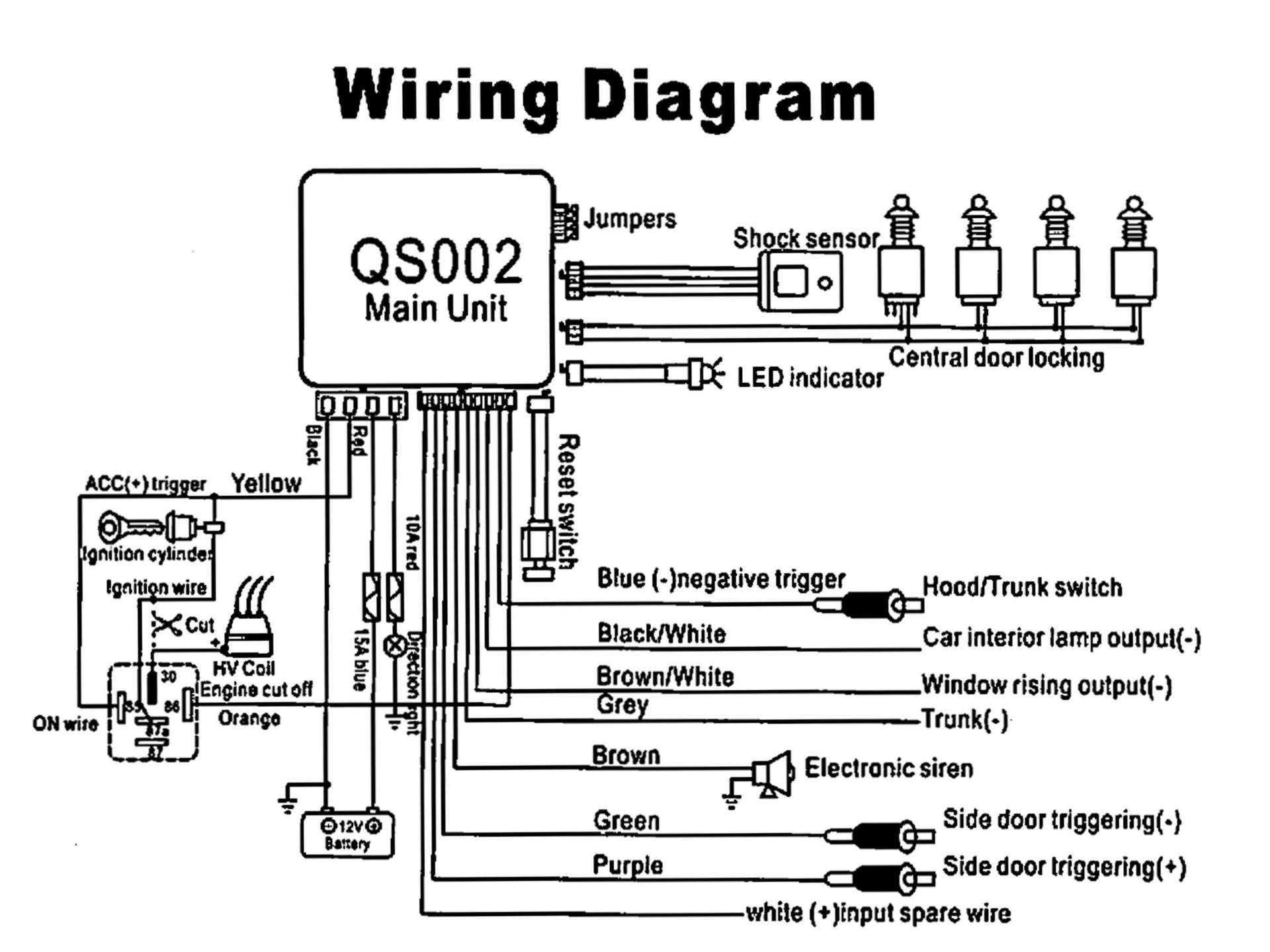
Understanding your car alarm's wiring diagram is crucial for a variety of reasons. Whether you're performing repairs, upgrading your existing system, diagnosing a malfunction, or simply aiming to expand your automotive knowledge, the diagram serves as a roadmap to the complex electrical network that protects your vehicle. Think of it as the blueprints to your car's security system. This article will guide you through interpreting these diagrams, focusing on practical applications and safety considerations.
Key Specs and Main Parts of a Car Alarm System
Before diving into the diagram itself, it's essential to understand the main components of a car alarm system. These components interact based on the wiring diagram, so knowing their function is essential. Most aftermarket systems include the following:
- Control Module (Brain): This is the central processing unit of the alarm system. It receives signals from the various sensors and actuators, processes them according to its programming, and then triggers the appropriate responses, such as sounding the siren or disabling the starter.
- Siren: The audible alarm that sounds when the system is triggered.
- Door, Hood, and Trunk Sensors: These sensors, typically utilizing switches or magnetic contacts, detect when these access points are opened. Some systems use the car's existing door trigger circuits.
- Shock Sensor: Detects impacts to the vehicle. Sensitivity is adjustable on most systems.
- Tilt Sensor: Detects if the car is being towed or jacked up.
- Starter Kill Relay (Immobilizer): Prevents the engine from starting when the alarm is armed. This is a crucial anti-theft feature.
- Parking Light Flash: Flashes the vehicle's parking lights to visually indicate that the alarm is armed or triggered.
- Remote Control (Key Fob): Allows you to arm, disarm, and control other functions of the alarm system remotely.
- LED Indicator: Provides a visual indication of the alarm's status (armed, disarmed, triggered).
- Wiring Harness: A collection of wires connecting all components.
Understanding Wiring Diagram Symbols
Car alarm wiring diagrams use a standardized set of symbols to represent electrical components, connections, and wire types. Learning these symbols is fundamental to interpreting the diagram correctly. Here's a breakdown of common symbols you'll encounter:
- Wires: Represented by solid lines. Different colors indicate different functions. For example, red might be used for power (+12V), black for ground, and other colors for various signal wires. The thickness of the line doesn't typically relate to wire gauge in most automotive diagrams, but you should always confirm wire gauge based on the current it needs to carry.
- Ground: Typically represented by a symbol resembling stacked horizontal lines or a triangle pointing downwards. This indicates the connection point for the negative terminal of the vehicle's electrical system.
- Power (+12V): Often depicted with a "+" symbol or labeled as "BATT" (Battery) or "IGN" (Ignition).
- Fuses: Shown as a zig-zag line enclosed within a rectangle. The amperage rating is usually indicated near the fuse symbol (e.g., 10A).
- Relays: Represented by a coil and a switch mechanism. The coil energizes when voltage is applied, causing the switch to change position. Normally Open (NO) and Normally Closed (NC) contacts are typically labeled.
- Switches: Depicted as a break in a line with an arrow indicating the direction of movement. The switch can be SPST (Single Pole Single Throw), SPDT (Single Pole Double Throw), DPST (Double Pole Single Throw), or DPDT (Double Pole Double Throw), depending on the number of poles and throws.
- Sensors: The specific symbol varies depending on the sensor type (e.g., door sensor, shock sensor). The diagram should clearly label the type of sensor.
- Connectors: Indicated by circles or squares where wires connect. The connector number is usually labeled for easy identification.
Color Coding: Wire colors are critically important in automotive wiring diagrams. While specific colors can vary by manufacturer and system, some common conventions exist:
- Red: Typically indicates +12V power.
- Black: Usually represents ground.
- Yellow: Often used for ignition-switched power.
- Blue: Frequently used for alarm trigger wires.
- Green: Common for door trigger wires.
- White: Can be used for various signals, often requiring careful tracing to determine function.
How a Car Alarm System Works (Simplified)
The wiring diagram illustrates how the alarm system detects threats and responds accordingly. Here’s a simplified overview of the process:
- Arming the System: When you arm the alarm using the remote, the control module enters an armed state. It begins monitoring the various sensors.
- Sensor Activation: If a door is opened, the hood is tampered with, a shock is detected, or the car is tilted, the corresponding sensor sends a signal to the control module.
- Control Module Processing: The control module receives the signal from the sensor and verifies that the system is armed.
- Alarm Trigger: If the system is armed and a sensor is triggered, the control module activates the alarm outputs. This typically includes:
- Siren Activation: The control module sends a voltage signal to the siren, causing it to sound.
- Starter Kill Activation: The starter kill relay is activated, interrupting the circuit that allows the engine to start.
- Parking Light Flash: The parking lights are flashed to attract attention.
- Optional Outputs: Some systems may have additional outputs that can be used to control other devices, such as door locks or window closures.
- Disarming the System: Disarming the system with the remote deactivates the alarm outputs and allows the engine to start.
Real-World Use: Basic Troubleshooting
Wiring diagrams are invaluable for troubleshooting car alarm problems. Here are a few common scenarios:
- Alarm Falsely Triggering: Use the diagram to identify the sensors connected to the control module. Disconnect each sensor one at a time to isolate the faulty sensor. Check the wiring to the suspect sensor for shorts or breaks. Common culprits are door pin switches that have corroded or shock sensors set too sensitively.
- Alarm Not Arming/Disarming: Check the power and ground connections to the control module. Verify that the remote control battery is good. Test the remote's signal strength with a multimeter (if possible) or by trying a known good remote.
- Siren Not Working: Check the siren's power and ground connections. Use a multimeter to verify that the control module is sending a signal to the siren when the alarm is triggered. Test the siren itself by applying direct voltage.
- Starter Kill Not Working: Use the diagram to identify the starter kill relay and its connections. Verify that the relay is functioning correctly by testing it with a multimeter. Check the wiring between the relay and the starter circuit.
Safety Precautions
Working with automotive electrical systems can be dangerous. Take the following precautions:
- Disconnect the Battery: Always disconnect the negative terminal of the battery before working on the electrical system. This will prevent accidental shorts and potential electrical shocks.
- Use Proper Tools: Use insulated tools designed for automotive electrical work.
- Work in a Well-Ventilated Area: If you are soldering or using solvents, work in a well-ventilated area to avoid inhaling harmful fumes.
- Be Careful with Wires: Avoid cutting or splicing wires unnecessarily. Use proper crimping and soldering techniques to ensure secure and reliable connections.
- Fuses: Never replace a fuse with a higher amperage rating than specified. This can overload the circuit and cause a fire.
The starter kill relay and the siren are often connected to circuits with high current or voltage. Exercise extra caution when working on these components.
Understanding and utilizing the car alarm wiring diagram is paramount for both preventative maintenance and corrective repairs. By familiarizing yourself with the key components, symbols, and troubleshooting tips outlined above, you can confidently tackle many common alarm system issues. Always prioritize safety and double-check your work. Remember, a well-understood wiring diagram is your best tool in maintaining a functioning and reliable car alarm system.
We have a detailed wiring diagram file ready for you to download. Please reach out, and we'll provide the link. Good luck with your project!