
Car Alternator To Motor Wiring Diagram
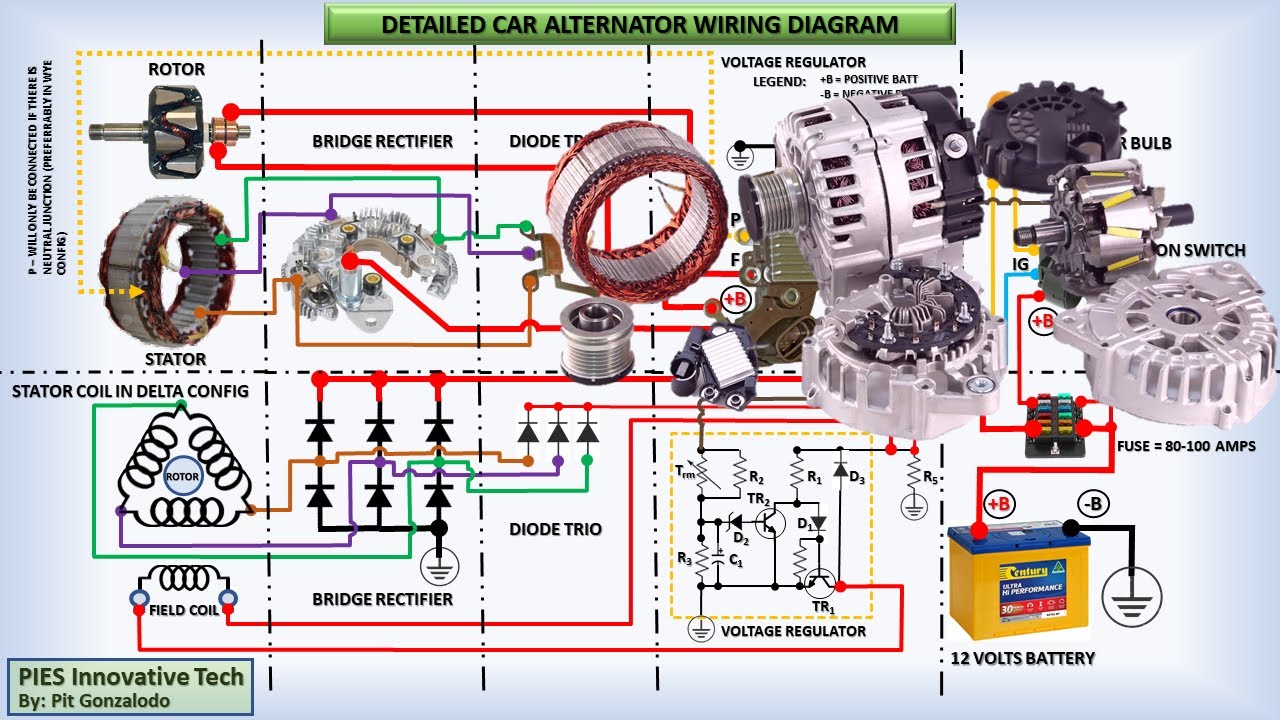
Alright, let's dive into the world of car alternators and how to wire them up as a motor. This is a project that comes up more often than you might think, whether you're experimenting with electric go-karts, building a small generator, or simply trying to understand the inner workings of your vehicle's charging system. Having a clear wiring diagram is crucial, and we've got one you can download later on. First, let’s discuss why understanding this is important.
Purpose
A solid understanding of an alternator-to-motor wiring diagram is invaluable for several reasons:
- Repair and Maintenance: Knowing how the alternator interacts with the rest of the electrical system can save you money on repairs. You'll be able to diagnose issues more effectively and even perform some repairs yourself.
- Educational Value: Understanding the principles behind alternator operation is a fantastic way to deepen your automotive knowledge. It helps you grasp concepts like electromagnetism, rectification, and voltage regulation.
- DIY Projects: As mentioned earlier, alternators can be repurposed into electric motors for various projects. A clear wiring diagram is absolutely essential for a successful conversion.
- Troubleshooting: Is your car battery not charging correctly? Understanding the wiring is the first step in tracing down the electrical fault.
Key Specs and Main Parts
Before we get into the diagram itself, let's review the key specs and components of a typical automotive alternator:
Key Specs
- Voltage: Most automotive alternators are 12V, although some heavy-duty vehicles use 24V systems.
- Amperage: Alternators are rated in amps (A), indicating their maximum current output. Common ratings range from 60A to 150A or even higher in modern vehicles with heavy electrical loads.
- RPM Range: Alternators are designed to operate within a specific RPM range, typically dictated by the engine's operating speed and the pulley ratio.
Main Parts
- Stator: The stationary part of the alternator that contains the windings where electricity is generated. It's essentially a coil of wires.
- Rotor (or Field Coil): The rotating part of the alternator that creates a magnetic field when energized. This magnetic field interacts with the stator to produce electricity. Also called the armature.
- Rectifier (Diode Bridge): Converts the AC (alternating current) generated by the stator into DC (direct current), which is required by the car's electrical system. These are heavy duty diodes, typically six of them.
- Voltage Regulator: Maintains a constant output voltage (usually around 14.4V) to prevent overcharging the battery and damaging other electrical components. Most modern alternators have internal voltage regulators.
- Brushes: Conduct electricity to the rotor to energize the field coil. They wear down over time and are a common cause of alternator failure.
- Pulley: Connects the alternator to the engine via a belt, transferring mechanical energy to the alternator.
- Housing: Provides physical support and protection for the internal components.
Symbols in the Wiring Diagram
Understanding the symbols used in the wiring diagram is critical. Here's a breakdown of common symbols you'll encounter:
- Solid Lines: Represent wires or conductors. The thickness of the line may indicate the wire gauge (thicker lines usually mean thicker wires).
- Dashed Lines: Often represent ground connections or shielded wires.
- Colors: Wires are color-coded to help identify their function. Common colors include red (power), black (ground), blue, green, and yellow (signal wires). The diagram key will explain what each color represents in that specific circuit.
- Circles: Usually indicate connection points or terminals.
- Squares/Rectangles: Often represent components such as relays, fuses, or the alternator itself.
- Ground Symbol: Looks like an upside-down Christmas tree or stacked horizontal lines. Indicates a connection to the chassis ground.
- Diode Symbol: A triangle pointing to a line. Shows the direction of current flow through the rectifier.
- Resistor Symbol: A zig-zag line. Represents a component that resists the flow of current.
- Alternator Symbol: Typically a circle with an "AC" symbol inside.
How It Works (Alternator to Motor Conversion)
The core principle behind converting an alternator into a motor involves energizing the stator windings directly. Here's a simplified explanation:
- Normally: The alternator takes rotational mechanical energy from the engine (via the belt) and converts it to electrical energy. The rotor spins, creating a magnetic field that induces current in the stator windings. This AC current is then rectified into DC.
- Reversed Operation: To use it as a motor, we apply DC voltage to the stator windings. This creates a magnetic field within the stator. By controlling the timing and polarity of the current applied to the stator, we can interact with the rotor's magnetic field and cause it to rotate.
- External Control: Converting an alternator to a motor necessitates external control. You need an external power supply (battery) and a controller (usually some type of electronic speed controller or ESC) to manage the current flowing to the stator windings. This controller will determine the speed and direction of the "motor."
Important Considerations for Motor Conversion:
- Commutation: Unlike a traditional DC motor with a commutator, an alternator lacks this mechanical switching mechanism. You'll need to simulate commutation electronically using your external controller.
- Overheating: Running an alternator as a motor can generate significant heat. Proper cooling (e.g., forced air cooling) is essential to prevent damage.
- Voltage and Current Limits: Carefully research the voltage and current limits of your specific alternator model before attempting a conversion. Exceeding these limits can lead to catastrophic failure.
Real-World Use – Basic Troubleshooting Tips
Even if you're not converting an alternator to a motor, understanding the wiring diagram can help with troubleshooting charging system issues in your car:
- No Charging: If your battery isn't charging, start by checking the voltage at the battery terminals with the engine running. It should be around 13.5V to 14.5V. If it's significantly lower (e.g., 12V or less), the alternator may be faulty. Consult the wiring diagram to check the connections to the alternator.
- Warning Light: The battery warning light on your dashboard indicates a problem with the charging system. This could be due to a faulty alternator, a loose belt, or a wiring issue. Again, use the diagram to trace the circuit and identify potential problems.
- Overcharging: If your battery is constantly boiling or your electrical components are failing prematurely, the alternator may be overcharging. This is often caused by a faulty voltage regulator.
- Voltage Drops: Use a multimeter to check for voltage drops along the wiring harness connected to the alternator. Excessive voltage drops indicate corroded connections or damaged wires.
Safety – Highlight Risky Components
Working with automotive electrical systems can be dangerous. Here are some key safety precautions:
- Disconnect the Battery: Always disconnect the negative battery terminal before working on any electrical components. This prevents accidental shorts and potential electrocution.
- Wear Safety Glasses: Protect your eyes from flying debris.
- Use Insulated Tools: Use tools with insulated handles to prevent electrical shocks.
- Be Mindful of Heat: Alternators can get very hot, especially when operating under heavy load. Allow the alternator to cool down before handling it.
- High Current: The high currents involved in the charging system can cause severe burns. Avoid touching exposed wires or terminals while the engine is running.
- Capacitors: Some alternators have capacitors which can hold a charge even after the power is disconnected. Discharge any capacitor before touching it.
Risk of Electrocution: While a car's 12V system is generally considered low voltage, it can still deliver a significant shock, especially if you have wet hands or are standing on a damp surface. Exercise extreme caution.
Remember, if you're not comfortable working with electrical systems, it's always best to consult a qualified mechanic.
Now, to help you further, we have a comprehensive car alternator to motor wiring diagram available for download. It provides a detailed overview of the wiring connections and components involved in a typical alternator conversion. Understanding and correctly interpreting this diagram will be crucial for your project's success.