
Car Dual Battery Isolator Wiring Diagram
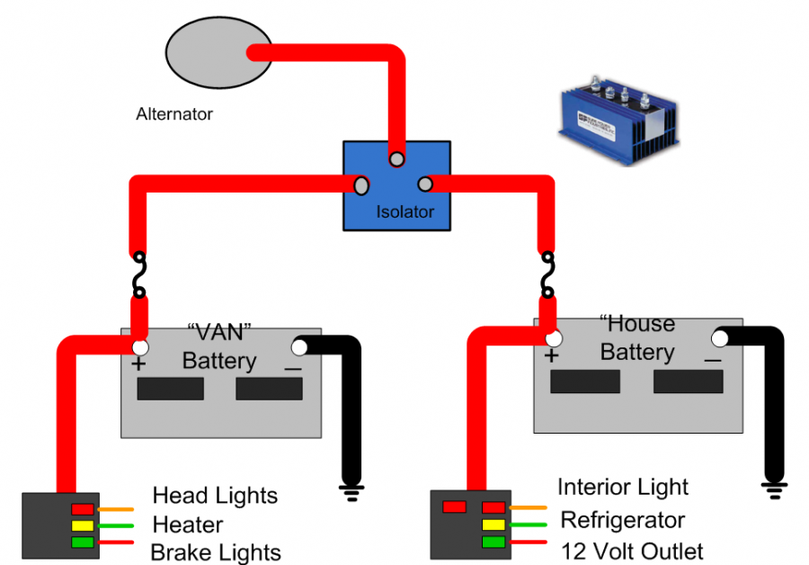
So, you're thinking about adding a dual battery system to your rig? Smart move. Whether you're powering a serious off-road adventure, setting up a mobile workstation, or just want the peace of mind that comes with a backup power source, a dual battery setup is a game changer. But before you dive in, understanding the wiring diagram for a dual battery isolator is absolutely crucial. This article will break down everything you need to know, from the purpose and key components to troubleshooting and safety.
Why Bother with the Diagram?
Let's face it, electrical work can be intimidating. A wiring diagram isn't just a pretty picture; it's your roadmap. Specifically in this case, understanding the dual battery isolator wiring diagram is vital for:
- Successful Installation: Following the diagram ensures you connect everything correctly, avoiding costly mistakes and potential damage.
- Troubleshooting: When things go wrong (and they sometimes do!), the diagram helps you pinpoint the problem quickly. Is the auxiliary battery not charging? The diagram will guide you to the potential culprit.
- Future Modifications: Want to add more accessories? The diagram provides a solid foundation for expanding your system.
- Understanding Your System: Even if you hire someone to install the system, understanding the diagram empowers you to know how it works and maintain it properly.
Ultimately, it’s about taking control of your project and ensuring a reliable and safe electrical system. Consider this knowledge essential for anyone tackling this type of modification.
Key Specs and Main Parts
Before we get into the specifics of the diagram, let's review the core components of a dual battery system and some key specifications to consider.
Main Parts:
- Starting Battery: Your vehicle's primary battery, responsible for starting the engine and powering essential systems.
- Auxiliary Battery (or House Battery): A secondary battery dedicated to powering accessories like lights, refrigerators, inverters, and other electrical devices. Deep cycle batteries are generally preferred for this application, as they are designed for repeated deep discharges.
- Battery Isolator: The heart of the system. Its job is to connect and disconnect the starting and auxiliary batteries. The goal is to allow the auxiliary battery to power accessories without draining the starting battery, ensuring you can always start your vehicle. Common types include:
- Solenoid-Based Isolators: A heavy-duty relay controlled by the ignition. When the ignition is on, the solenoid closes, connecting the batteries for charging. When the ignition is off, the batteries are isolated.
- Automatic Charging Relays (ACRs): Similar to solenoids, but they automatically connect the batteries based on voltage levels. They're more sophisticated and often preferred.
- Solid State Isolators: Utilizes diodes to allow current to flow in only one direction, but these suffer from voltage drop and are becoming less common.
- Fuses and Circuit Breakers: Crucial for protecting your system from overloads and short circuits. They should be placed as close to the batteries as possible.
- Wiring: Heavy-gauge wiring is essential to handle the high currents involved. Size your wiring according to the amperage requirements of your accessories and the distance of the run. Voltage drop can become a significant issue if wiring is undersized.
- Grounding Cables: Just as important as positive cables. Ensure all components are properly grounded to the chassis.
Key Specs:
- Voltage: Typically 12V for most vehicles. Make sure all components are compatible.
- Amperage: The maximum current your isolator and wiring can handle. This needs to exceed the combined amperage draw of your accessories.
- Battery Capacity (Amp-Hours): The amount of energy stored in your batteries. Choose a capacity that meets your power needs.
- Wire Gauge: Determined by the amperage and length of the wire run. Consult a wire sizing chart.
- Isolator Activation Voltage: For ACRs, this is the voltage at which the isolator connects the batteries.
Decoding the Wiring Diagram: Symbols, Lines, and Colors
The wiring diagram is a symbolic representation of your electrical system. Understanding these symbols is key to interpreting the diagram correctly. Here's a breakdown of common elements:
Lines:
- Solid Lines: Represent wires. The thickness of the line may indicate the wire gauge, but always double-check the diagram's legend.
- Dashed Lines: Often indicate control wires or connections that are not power-carrying conductors.
- Arrows: Show the direction of current flow.
Colors:
Wire colors are often standardized to help with identification. Here are some common conventions:
- Red: Positive (+) power wire.
- Black: Negative (-) ground wire.
- Blue/Yellow/White: Often used for control wires, such as the ignition switch signal to the isolator. Check the specific diagram for color codes.
- Green: Another common color for grounding, especially when connecting to the chassis.
Icons:
- Battery: Represented by a series of parallel lines, with a + and - sign indicating polarity.
- Fuse: A zigzag line inside a rectangle.
- Circuit Breaker: Similar to a fuse, but often with a toggle switch symbol.
- Solenoid/Relay: A coil symbol with a switch.
- Ground: A series of downward-pointing lines, often resembling an upside-down Christmas tree.
- Switch: Represented by a line with a break in it, and an arm that can close the connection.
Always refer to the specific wiring diagram's legend for accurate interpretations, as conventions can vary slightly.
How a Dual Battery Isolator System Works
The basic principle is simple: to isolate the starting battery from the auxiliary battery while allowing both to be charged by the alternator. Here's a simplified explanation of how a solenoid-based system works:
- Engine Off: When the engine is off, the ignition switch is open, and the solenoid is de-energized. The contacts within the solenoid are open, isolating the starting battery from the auxiliary battery. The auxiliary battery can now power accessories without affecting the starting battery.
- Engine On: When the engine is started, the ignition switch sends a signal to the solenoid. The solenoid coil energizes, closing the contacts. This connects the starting and auxiliary batteries in parallel.
- Charging: With the batteries connected, the alternator charges both batteries simultaneously. Once the starting battery is fully charged, the excess charging current flows to the auxiliary battery.
ACRs work similarly, but instead of relying on the ignition switch, they monitor the voltage of both batteries. When the voltage of either battery reaches a certain threshold (typically around 13.2V), the ACR connects the batteries. When the voltage drops below a threshold (typically around 12.7V), the ACR disconnects them.
Real-World Use and Basic Troubleshooting
Here are some common issues you might encounter and how the wiring diagram can help you diagnose them:
- Auxiliary Battery Not Charging:
- Check the fuses near the isolator and the batteries. Blown fuses are a common cause.
- Verify the isolator is functioning. If it's a solenoid-based isolator, you should hear a click when the ignition is turned on. If it's an ACR, check the voltage readings on both sides.
- Inspect the wiring for loose connections or corrosion, especially at the battery terminals and grounding points. Use the wiring diagram to trace the path of the charging current.
- Check your ground points. A bad ground can prevent proper charging.
- Starting Battery Drained:
- Confirm the isolator is actually isolating the batteries when the engine is off. A faulty isolator might be allowing the auxiliary battery to drain the starting battery.
- Check for parasitic draws on the starting battery, such as a faulty alarm system or a light left on.
- Accessories Not Working:
- Check the fuses in the accessory circuits.
- Verify the auxiliary battery is fully charged.
- Inspect the wiring to the accessories for loose connections or damage.
Safety First!
Working with automotive electrical systems can be dangerous. Here are some essential safety precautions:
- Disconnect the Negative Terminal: Always disconnect the negative terminal of the starting battery before working on the electrical system. This prevents accidental short circuits.
- Wear Safety Glasses: Protect your eyes from sparks and debris.
- Use Insulated Tools: Prevent shocks and short circuits.
- Double-Check Your Work: Before reconnecting the battery, carefully review your wiring to ensure everything is connected correctly.
- Fuses are Your Friends: Never bypass fuses or use a higher amperage fuse than recommended. They're there to protect your system from damage and prevent fires.
Batteries contain corrosive acid and can release explosive gases. Work in a well-ventilated area and avoid sparks or flames near the batteries.
This information provides a solid starting point for understanding dual battery isolator wiring diagrams. Remember that specific diagrams will vary depending on the brand and type of isolator you are using. Always refer to the manufacturer's documentation for the most accurate and up-to-date information.
I've put together a downloadable wiring diagram template that you can use as a starting point. It's a general template, but it should give you a good visual representation to work with. We have the file, and you can download the diagram, which will help as you tackle your project.