Car Electrical Wiring Repair Near Me
Alright, let's talk about car electrical wiring repair. Whether you're tackling a faulty tail light, adding some custom lighting, or just trying to diagnose a gremlin in your engine, understanding your car's electrical system is absolutely crucial. This isn't just about knowing which wire goes where; it's about safely and effectively diagnosing and resolving electrical issues. And a good wiring diagram is your best friend.
Purpose: Your Roadmap to Automotive Electrical Success
A car electrical wiring diagram isn't just a pretty picture; it's a comprehensive roadmap of your car's entire electrical system. It's the key to:
- Repairing Faults: Tracing circuits to find shorts, opens, or high resistance points. Forget blindly poking around; a diagram guides you directly to the problem.
- Modifying and Upgrading: Adding aftermarket components like stereos, lights, or even performance enhancements requires tapping into the existing wiring. A diagram ensures you do it safely and correctly.
- Understanding System Function: Ever wondered how your car's computer talks to the fuel injectors? A wiring diagram shows you the connections and components involved, allowing you to understand the system's logic.
- Preventative Maintenance: By understanding the wiring layout, you can proactively inspect connectors and wiring harnesses for signs of damage or corrosion.
Key Specs and Main Parts of a Wiring Diagram
Before we dive into the symbols, let's break down the key components you'll find on a typical wiring diagram:
- Power Source: This is usually the battery (12V or 24V in trucks) and the alternator. These are represented by specific symbols and voltage indications.
- Fuses and Circuit Breakers: These are essential safety devices. They're designed to protect the wiring and components from overcurrent situations. A blown fuse is a symptom, not the problem itself. The diagram indicates the amperage rating of each fuse.
- Relays: Relays are electrically operated switches. They allow a low-current circuit (like a switch on your dashboard) to control a high-current circuit (like your headlights). Understanding relay circuits is critical for many repairs.
- Switches: These control the flow of electricity. Examples include ignition switches, headlight switches, and window switches.
- Loads: These are the devices that consume electrical energy, such as lights, motors, and solenoids.
- Grounds: The return path for the electrical current. A good, clean ground connection is absolutely essential for proper operation. Poor grounding is a common cause of electrical problems.
- Connectors: These allow wires to be easily connected and disconnected. The diagram will often show the location and pinout of connectors, which is invaluable for troubleshooting.
- Wiring Harnesses: Groups of wires bundled together and often protected by a sheath.
- Electronic Control Units (ECUs): Modern cars are full of computers. ECUs control everything from the engine to the transmission to the anti-lock brakes. The diagram will show the connections between the ECUs and the various sensors and actuators.
Decoding the Symbols: Lines, Colors, and Icons
Understanding the symbols used in a wiring diagram is like learning a new language. Here's a breakdown of the common elements:
- Lines: Solid lines represent wires. Thicker lines usually indicate wires carrying higher current.
- Colors: Wire colors are typically abbreviated using a standard code (e.g., BL = Blue, RD = Red, BK = Black, GN = Green, YL = Yellow, WH = White). These colors are *critical* for identifying wires in the harness.
- Ground Symbols: There are several variations, but they all indicate a connection to the vehicle's chassis, which serves as the electrical ground.
- Component Symbols: Each component (fuse, relay, switch, motor, etc.) has a specific symbol. A quick internet search for "automotive wiring diagram symbols" will reveal a comprehensive list.
- Splices: Points where multiple wires are joined together. These are often weak points in the system and can be prone to corrosion.
- Numbers and Letters: These indicate wire gauge (thickness) and circuit numbers. These identifiers are extremely useful for cross-referencing information within the diagram.
How It Works: Tracing the Circuit
The real power of a wiring diagram comes from your ability to trace circuits. Let's imagine you're troubleshooting a non-functioning headlight. Here's how you might use a diagram:
- Locate the Headlight Circuit: Find the section of the diagram that shows the headlight circuit.
- Identify the Power Source: Trace the circuit back to the power source (usually the battery, through a fuse).
- Check the Fuse: Verify that the fuse is intact. If it's blown, replace it and see if it blows again (indicating a short circuit).
- Follow the Wiring: Trace the wiring from the fuse to the headlight switch, then to the headlight itself. Pay attention to connectors along the way.
- Test for Voltage: Use a multimeter to check for voltage at various points along the circuit. If you have voltage at the switch but not at the headlight, the problem likely lies in the wiring or connectors between the switch and the headlight.
- Check the Ground: Verify that the headlight has a good ground connection.
The key is to follow the circuit systematically, using the diagram as your guide. Don't skip steps or make assumptions!
Real-World Use: Basic Troubleshooting Tips
Here are a few practical troubleshooting tips to keep in mind:
- Start Simple: Check the obvious things first, like fuses, bulbs, and connectors.
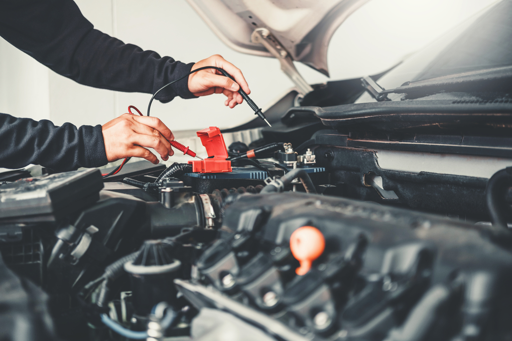
- Use a Multimeter: A multimeter is an indispensable tool for electrical troubleshooting. Learn how to use it to measure voltage, current, and resistance.
- Check for Voltage Drops: A voltage drop indicates resistance in the circuit. This can be caused by corrosion, loose connections, or damaged wiring.
- Isolate the Problem: If you suspect a short circuit, try disconnecting components one at a time to see if the short disappears.
- Don't Overlook Grounds: As mentioned before, poor grounding is a very common cause of electrical problems. Clean and tighten all ground connections.
Safety: Highlighting Risky Components
Working with automotive electrical systems can be dangerous if you're not careful. Here are some safety precautions:
- Disconnect the Battery: Always disconnect the negative battery cable before working on the electrical system. This will prevent accidental shorts and potential shocks.
- Be Careful with Airbags: Airbag systems are electrically triggered. If you're working near an airbag module, disconnect the battery and wait at least 10 minutes before proceeding. Consult your car's service manual for specific instructions.
- Avoid Working in Wet Conditions: Water and electricity don't mix.
- Use Proper Tools: Use insulated tools designed for electrical work.
- Don't Overload Circuits: When adding aftermarket components, make sure you're not exceeding the current capacity of the existing wiring. Use relays to control high-current devices.
High-energy components like the ignition system and fuel injection system can deliver dangerous shocks. Proceed with extreme caution and always disconnect the battery!
Working with electricity can be dangerous if you are not trained. If you are not comfortable performing electrical repairs, consult a qualified automotive electrician.
Understanding car electrical wiring repair and how to read diagrams is a valuable skill for any car enthusiast. With a little knowledge and the right tools, you can tackle many common electrical problems yourself. Remember to always prioritize safety and consult a professional if you're unsure about anything.