Car Ignition System Vw Ignition Switch Wiring Diagram
Okay, let's dive into the VW ignition switch wiring diagram. This guide is tailored for those of you who are comfortable turning a wrench and want to understand, troubleshoot, or even modify your Volkswagen's ignition system. We'll break down the diagram's elements, explain how it all works, and offer some practical tips. Knowing this stuff can save you money on repairs and empower you to diagnose problems yourself. We even have a downloadable diagram available for you.
Purpose of Understanding the VW Ignition Switch Wiring Diagram
Why bother with this diagram in the first place? There are several reasons:
- Repair and Diagnosis: The most obvious. If your VW isn't starting, or the electrical accessories aren't working correctly, the ignition switch or its wiring could be the culprit. The diagram allows you to trace circuits, identify faulty connections, and pinpoint the problem.
- Modification and Customization: Maybe you're adding aftermarket accessories, installing a remote start system, or even doing a complete rewire of your classic VW. Understanding the ignition switch wiring is crucial for integrating new components safely and effectively.
- Learning and Education: Even if you're not facing a specific problem, studying the diagram helps you understand the fundamental principles of automotive electrical systems. This knowledge can be invaluable for future troubleshooting and maintenance.
Key Specs and Main Parts
Before we dissect the diagram, let's familiarize ourselves with the key components involved:
- Ignition Switch: This is the central hub of the system. It's a multi-position switch that controls power to various circuits based on the key's position (Lock, Accessory, On, Start).
- Battery: The source of all electrical power. Typically, a 12V system.
- Starter Motor: The electric motor that cranks the engine.
- Solenoid: An electromechanical switch that engages the starter motor and provides it with high current.
- Fuses and Circuit Breakers: Protective devices that prevent overcurrent and protect circuits from damage. These are critical for safety.
- Relays: Electrically operated switches that allow a low-current circuit (e.g., the ignition switch) to control a high-current circuit (e.g., the starter motor).
- Wiring Harness: A bundle of wires that connect all the components.
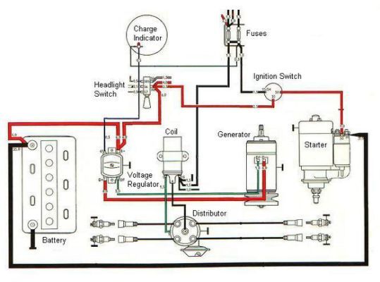
Decoding the Diagram: Symbols, Lines, and Colors
Understanding the symbols and conventions used in the wiring diagram is essential for interpreting it correctly.
- Lines: These represent wires. A solid line indicates a direct connection, while a dashed line may indicate a hidden connection or a wire that's part of a larger harness. Line thickness doesn't usually indicate wire gauge, but it's best to check the diagram's key or legend.
- Colors: Each wire is color-coded for easy identification. Common colors include red (battery positive), black (ground), brown (ground), yellow (ignition), blue (lights), and green (various accessories). The diagram's legend will provide the specific color code for your VW model. For example, "RD/BK" means a red wire with a black stripe.
- Symbols: These represent electrical components. Here are a few common ones:
- Battery: A series of short and long parallel lines.
- Resistor: A zig-zag line.
- Capacitor: Two parallel lines.
- Fuse: A wavy line inside a rectangle.
- Relay: A coil symbol and a switch symbol.
- Ground: Typically three lines decreasing in length, resembling an inverted pyramid.
- Numbers and Letters: These identify specific wires, terminals, and connectors. Refer to the diagram's key or legend for their meaning. Often, these numbers relate to standardized DIN numbers for automotive electrical systems.
How the Ignition System Works: A Step-by-Step Overview
Let's trace the flow of electricity through the ignition system to understand how it operates. The basic sequence is:
- Key in 'Lock' Position: No circuits are energized (except maybe a constant-on circuit for things like the clock or radio memory).
- Key in 'Accessory' (ACC) Position: Power is supplied to circuits like the radio, cigarette lighter, and sometimes the power windows.
- Key in 'On' Position: Power is supplied to the ignition coil (or ignition module in newer vehicles), fuel pump, and other essential engine management components. The engine is now ready to start.
- Key in 'Start' Position: This energizes the starter motor solenoid, which then engages the starter motor to crank the engine. Once the engine starts, you release the key, and it springs back to the 'On' position.
The wiring diagram shows the exact connections for each of these positions. It illustrates which wires are connected to each other in each position of the ignition switch. Understanding this flow is key to troubleshooting.
Real-World Use: Basic Troubleshooting Tips
Here are some common problems and how the wiring diagram can help you diagnose them:
- No Start: Check the battery voltage first! Then, use the diagram to trace the starter circuit. Is the starter solenoid receiving power when the key is in the 'Start' position? If not, check the ignition switch, the wiring, and any relevant fuses or relays. A multimeter is your best friend here.
- No Power to Accessories: If you have no radio or other accessories, check the fuse that protects that circuit. If the fuse is good, use the diagram to trace the accessory circuit back to the ignition switch. The switch itself might be faulty.
- Engine Cranks But Doesn't Start: This could be a fuel or ignition problem. Use the diagram to check the power supply to the fuel pump and the ignition coil. A faulty ignition switch could be preventing these components from receiving power.
When troubleshooting, always start with the simplest things first: fuses, connections, and battery voltage. Then, systematically work your way through the circuit using the wiring diagram as your guide.
Safety First! Handling Risky Components
Working with automotive electrical systems can be dangerous. Here are some key safety precautions:
- Disconnect the Battery: Always disconnect the negative terminal of the battery before working on the electrical system. This prevents accidental shorts and potential damage or injury.
- Work in a Well-Ventilated Area: Batteries can produce explosive gases.
- Use the Right Tools: Use properly insulated tools to avoid electrical shock.
- Be Careful with Fuses: Never replace a fuse with one of a higher amperage rating. This can overload the circuit and cause a fire.
- Identify High-Current Circuits: Be extra cautious when working with circuits that carry high current, such as the starter circuit.
The starter solenoid and associated wiring can deliver a massive amount of current, enough to cause serious burns or even death. Treat these components with respect.
By understanding the VW ignition switch wiring diagram and following proper safety procedures, you can confidently diagnose and repair electrical problems in your vehicle. Remember to double-check your work and consult a qualified mechanic if you're unsure about anything.
You can now download the VW Ignition Switch Wiring Diagram here. This detailed diagram will be an invaluable resource as you work on your VW. Good luck, and happy wrenching!