Car Stereo 2010 Dodge Charger Radio Wiring Diagram
So, you're looking to delve into the audio system of your 2010 Dodge Charger. Whether you're planning an upgrade, troubleshooting a faulty speaker, or just trying to understand the inner workings of your car's electronics, a radio wiring diagram is an absolutely essential tool. Think of it as a roadmap to your Charger's audio brain. We've got the complete diagram ready for you to download at the end of this article, but first, let's break down what you'll find and how to use it.
Purpose: Decoding the 2010 Dodge Charger Radio Wiring
Why bother with a wiring diagram? Well, several reasons. First, if you're experiencing issues like speakers cutting out, no sound, or even electrical problems that seem related to the audio system, the diagram can help you pinpoint the source of the problem. It allows you to systematically trace wires, check connections, and identify faulty components. Second, it's indispensable when installing an aftermarket head unit, amplifier, or other audio accessories. You need to know which wire does what to avoid frying something (or yourself!). Finally, understanding the diagram helps you learn about your car's electrical system, giving you a better overall understanding of your vehicle's mechanics.
Key Specs and Main Parts
The 2010 Dodge Charger, depending on the trim level, came with a few different audio configurations. The base model usually featured a standard AM/FM radio with a CD player and four speakers. Higher trims could include a premium sound system with an amplifier, subwoofer, and more speakers. Regardless of the exact configuration, the core components remain the same. Here’s a breakdown:
- Head Unit: This is the central control unit, often referred to as the radio or receiver. It handles AM/FM radio reception, CD playback (if equipped), and often includes auxiliary input or USB ports. It also provides the necessary power and signal output to the speakers.
- Speakers: Typically located in the doors and sometimes in the rear deck, speakers convert the electrical signals from the head unit (or amplifier) into audible sound.
- Amplifier (if equipped): Some models feature a dedicated amplifier to boost the audio signal for louder and cleaner sound. This is common in premium sound systems. The amplifier is usually located in the trunk or under a seat.
- Wiring Harness: This is a bundle of wires connecting the head unit to the car's electrical system and speakers. It includes power, ground, speaker outputs, and control signals.
- Antenna: The antenna receives radio signals.
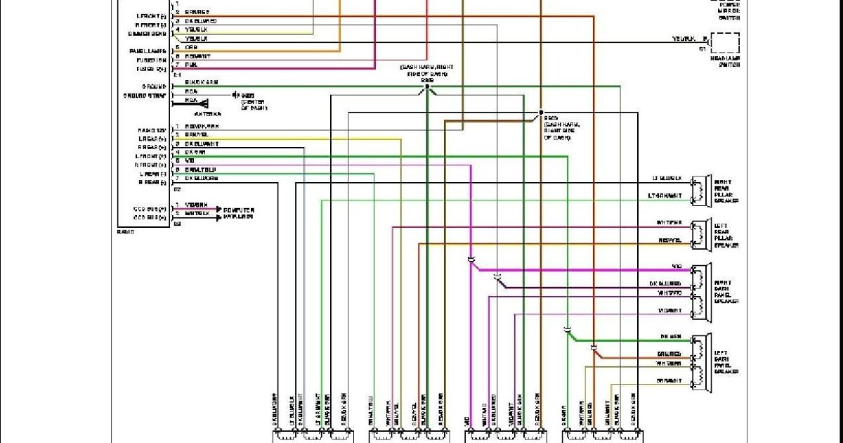
The wiring diagram will show all these components and how they're interconnected. It also includes critical information like wire colors, connector types, and circuit routing.
Symbols: Reading the Electrical Roadmap
Understanding the symbols used in the diagram is crucial. Let's decipher the common ones:
- Lines: Solid lines represent wires, while dashed lines might indicate shielded cables or signal paths. Line thickness can sometimes represent wire gauge (thicker lines = thicker wires).
- Colors: Each wire is identified by a specific color code, such as "RD" for red, "BK" for black, "WH" for white, "GN" for green, and so on. These color codes are essential for identifying the correct wires during installation or troubleshooting. Note: Color codes might have combinations, such as "WH/BK" for white with a black stripe.
- Connectors: Connectors are represented by various symbols, often rectangular or circular shapes with pins or sockets. The diagram will usually indicate the connector type and the pin numbers to help you identify the correct connection points.
- Ground Symbols: Ground connections are typically depicted as a series of horizontal lines decreasing in length, resembling an inverted pyramid.
- Component Symbols: Each component (resistor, capacitor, diode, etc.) has a unique symbol that represents its function. For this diagram you will mostly see speaker symbol and power source symbol.
- Fuses: Fuses are shown as small rectangular boxes with a line running through them. They protect the circuit from overcurrent. Knowing the fuse location and rating is vital for safety.
Pay close attention to the legend or key on the wiring diagram. It provides a complete explanation of all the symbols and abbreviations used.
How It Works: Following the Signal Path
The basic principle is simple: the head unit receives power and ground, processes audio signals (from radio, CD, etc.), and sends those signals to the speakers. In systems with an amplifier, the head unit sends a low-level signal to the amplifier, which boosts the signal and sends it to the speakers. The wiring diagram shows the exact path of the electrical current and audio signals. Here’s a simplified breakdown:
- Power Supply: The head unit receives power from the car's battery through a fused circuit. There are usually two power wires: one for constant power (to retain memory settings) and one for switched power (activated when the ignition is turned on).
- Ground: The head unit needs a solid ground connection to complete the circuit.
- Input Signal: The head unit receives audio input from various sources like radio antenna, CD player, auxiliary input or USB.
- Output Signal: The head unit outputs audio signals to the speakers (or to the amplifier in amplified systems). Each speaker has two wires: positive (+) and negative (-).
- Speaker Connections: The speakers are connected to the head unit (or amplifier) via speaker wires. It's crucial to maintain proper polarity (positive to positive, negative to negative) to avoid phase cancellation, which can result in poor sound quality.
By tracing the wires on the diagram, you can see how each component interacts with the others and understand the flow of electricity and audio signals.
Real-World Use: Basic Troubleshooting Tips
Here are a few common troubleshooting scenarios where a wiring diagram can be invaluable:
- No Sound: If you have no sound from any of the speakers, check the power and ground connections to the head unit. Also, check the fuse associated with the radio. The diagram will show you the fuse location.
- Speaker Cutting Out: If a single speaker is cutting out, check the speaker wire connections at the speaker and at the head unit (or amplifier). The diagram will help you identify the correct wires.
- Distorted Sound: Distorted sound can be caused by a blown speaker or a faulty amplifier. The diagram can help you trace the signal path to isolate the problem.
- Installing Aftermarket Head Unit: The diagram is essential for identifying the correct wires for power, ground, speakers, and other functions. Use a wiring harness adapter designed for your 2010 Dodge Charger to simplify the installation.
When troubleshooting, always start with the simplest checks first, such as fuses and connections. Use a multimeter to check for voltage and continuity.
Safety: Handle with Care
Working with car electronics can be dangerous if you're not careful. Here are a few important safety precautions:
- Disconnect the Battery: Always disconnect the negative terminal of the battery before working on any electrical components. This prevents accidental short circuits and electrical shocks.
- Fuse Box Safety: When checking fuses, use a fuse puller. Avoid touching the metal contacts with your fingers.
- Airbag System: Be extremely careful when working near the airbag system. Refer to the vehicle's service manual for specific instructions and precautions. Accidental airbag deployment can cause serious injury.
- High Voltage Components: Some components, such as the ignition system, can carry high voltage. Avoid touching these components when the engine is running.
Always double-check your work and consult a professional if you're unsure about any aspect of the repair or installation.
With this knowledge and the wiring diagram in hand, you're well-equipped to tackle most audio-related projects on your 2010 Dodge Charger. Remember to work carefully, follow the instructions, and prioritize safety.
To download the complete 2010 Dodge Charger radio wiring diagram, click HERE. This PDF contains all the information discussed in this article, along with detailed illustrations and connector pinouts. Happy wrenching!