
Car Stereo To Amplifier Wiring Diagram
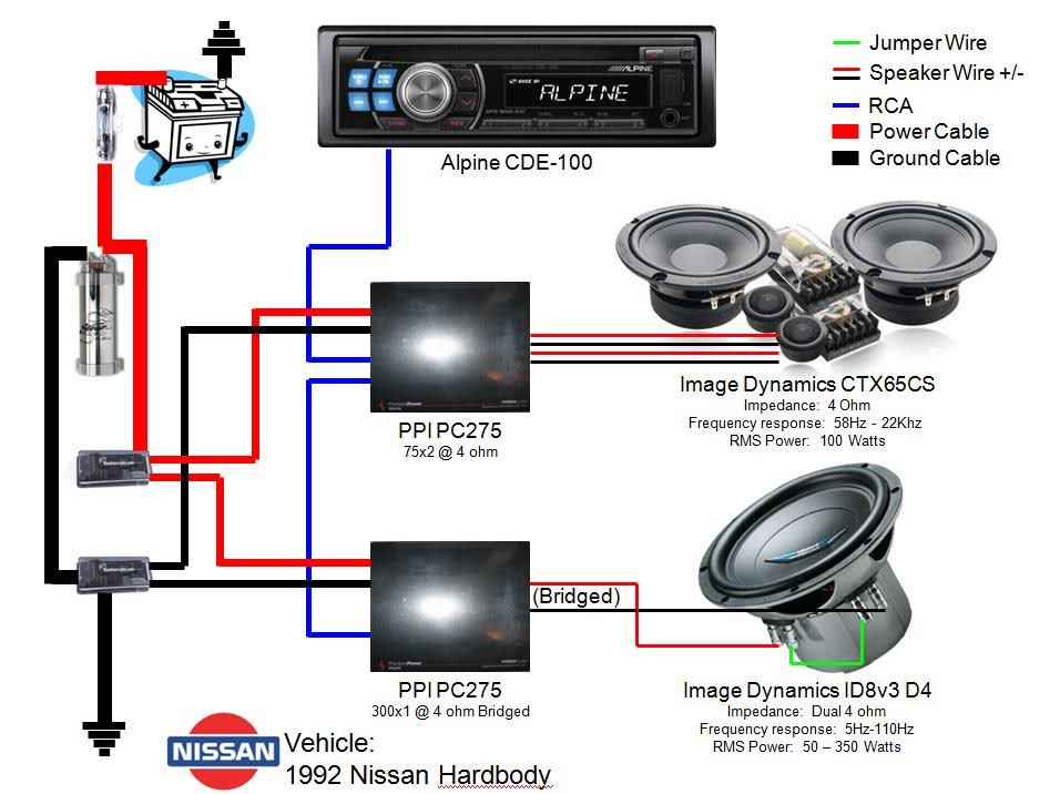
So, you're looking to beef up your car's sound system by adding an amplifier. That's fantastic! But before you start ripping apart your dashboard, it's crucial to understand the wiring. This article will guide you through understanding a car stereo to amplifier wiring diagram, equipping you with the knowledge to confidently tackle this upgrade or troubleshoot existing installations. Whether you're aiming for crystal-clear audio or bone-rattling bass, a solid grasp of the wiring is essential. And, yes, we've got a sample wiring diagram ready for you to download; more on that later.
Purpose: Why Understand the Wiring Diagram?
A car stereo to amplifier wiring diagram isn't just a pretty picture; it's your roadmap to audio bliss (or, potentially, audio disaster if ignored). Here's why it matters:
- Installation: The most obvious reason! Correctly wiring your amplifier to your head unit (car stereo) is paramount for proper functionality. A wiring diagram tells you exactly where each wire needs to go.
- Troubleshooting: Is your amplifier not turning on? Is there distortion in your speakers? A wiring diagram allows you to systematically trace the connections and identify the faulty wire or component.
- Repair: Maybe a wire has been cut or a connection has come loose. The diagram helps you repair the circuit properly, ensuring everything functions as designed.
- Modification: Want to add more speakers or change the gain settings? Understanding the initial wiring helps you modify the system safely and effectively without causing damage.
- Learning: Gaining a deeper understanding of car audio systems. Knowing the layout of the connections, allows you to better understand the purpose and limitations of the system.
Key Specs and Main Parts
Before diving into the diagram itself, let's review the key components you'll encounter:
- Head Unit (Car Stereo): The brains of the operation. It outputs the audio signal that the amplifier will boost. Look for RCA outputs (pre-outs) to connect to the amplifier, or speaker level outputs for amplifiers with speaker level inputs.
- Amplifier: The muscle! It takes the low-level signal from the head unit and amplifies it to drive your speakers. Consider the amplifier's power rating (RMS) and impedance (ohms) to match it with your speakers.
- Speakers: The voice! They convert the amplified electrical signal into sound waves. Match the speaker's impedance to the amplifier's output.
- Power Wire: This hefty wire carries power from the car's battery to the amplifier. It's usually a thick gauge wire (e.g., 4 AWG or 8 AWG) depending on the amplifier's power consumption.
- Ground Wire: This wire connects the amplifier to the car's chassis (metal body) for a solid ground connection. It should be the same gauge as the power wire.
- Remote Turn-On Wire (Remote Wire): This thin wire signals the amplifier to turn on when the head unit is powered. It connects from the head unit's remote output to the amplifier's remote input. This often uses a 16-18 AWG wire.
- RCA Cables (Interconnects): These cables carry the audio signal from the head unit's RCA outputs to the amplifier's RCA inputs. High-quality RCA cables help to minimize noise and interference.
- Speaker Wire: This wire connects the amplifier's speaker outputs to the speakers. Typically, 16 AWG wire is used for most car audio applications, but higher power systems may use 14 AWG or 12 AWG.
- Fuse: A safety device that protects the amplifier and wiring from overcurrent. It's usually located near the battery connection.
- Distribution Block (Optional): Used when powering multiple amplifiers. It splits the main power wire into multiple smaller gauge wires for each amplifier.
Symbols: Decoding the Wiring Diagram
Wiring diagrams use symbols to represent components and connections. Here's a breakdown of common symbols:
- Straight Lines: Represent wires. Thicker lines usually indicate larger gauge wires (power and ground).
- Dashed Lines: Can represent wires running through wiring harnesses or less important connections.
- Colored Lines: Each color usually corresponds to a specific wire function (e.g., red for power, black for ground, blue for remote turn-on). The color code is *crucial* for correct connections.
- Ground Symbol: Looks like an upside-down triangle or a series of decreasing horizontal lines. Indicates a connection to the car's chassis ground.
- Fuse Symbol: Looks like a wavy line or a box with a diagonal line through it. Indicates a fuse.
- RCA Connector Symbol: A circle with a smaller circle inside. Often labeled "L" for left and "R" for right.
- Speaker Symbol: Usually a circle with a plus (+) and minus (-) sign inside.
- Connectors and Terminals: Small circles, squares, or other shapes where wires connect to components.
Understanding Wire Colors: Different manufacturers use slightly different color codes, but some common conventions exist:
- Red: Power (+12V)
- Black: Ground (0V)
- Blue: Remote Turn-On
- White, Gray, Green, Purple: Usually designate speaker wires. Look for stripes on the wires to indicate positive (+) and negative (-) connections. Example: White with a black stripe may be left front negative.
How It Works: Signal Flow and Power Distribution
The basic flow of electricity and audio signal goes as follows:
- Power: The power wire connects directly to the car's battery (with a fuse nearby!). This provides the high current needed by the amplifier.
- Ground: The ground wire connects the amplifier to a solid metal part of the car's chassis, providing a return path for the current. A poor ground can cause all sorts of problems.
- Remote Turn-On: When you turn on your head unit, it sends a +12V signal through the remote wire to the amplifier. This tells the amplifier to power up.
- Audio Signal: The head unit sends a low-level audio signal (typically through RCA cables) to the amplifier's inputs.
- Amplification: The amplifier boosts the audio signal's voltage and current.
- Speaker Output: The amplified signal is sent to the speakers through speaker wires.
- Sound: The speakers convert the electrical signal into sound waves that you can hear.
Real-World Use: Basic Troubleshooting Tips
Armed with your wiring diagram, you can troubleshoot common issues:
- No Power to Amplifier:
Check the fuse on the power wire. Use a multimeter to verify you have +12V at the amplifier's power terminal and a good ground connection. Also, check the remote turn-on wire – is it getting +12V when the head unit is on? Verify the ground point is making good contact with bare metal. Scrape away any paint for a secure connection.
- Distortion:
Could be caused by a poor ground connection. Check the gain settings on the amplifier. Too high of a gain can cause clipping (distortion). Make sure your speakers are properly rated for the amount of power the amp is putting out.
- No Sound from One Speaker:
Check the speaker wire connections at both the amplifier and the speaker. Use a multimeter to check the speaker wire for continuity. Make sure that the speaker wire is properly seated in the terminals on the amplifier and speaker.
- Hum or Noise:
Ground loop problems are common. Try grounding the head unit to the same point as the amplifier. Also, check the RCA cables for damage or poor shielding. Run RCA cables away from power wires to minimize interference.
Safety: Proceed with Caution
Car audio wiring involves potentially dangerous components. Here's what to watch out for:
- Battery: Disconnect the negative terminal of the car battery before working on any wiring. This prevents shorts and potential electrical fires.
- Fuses: Always use the correct amperage fuse. Using a fuse with a higher amperage can defeat the protection it offers.
- Wiring: Use properly sized wire for the current draw of your amplifier. Undersized wire can overheat and cause a fire. Ensure wires are properly insulated and protected from sharp edges to prevent shorts.
- Airbags: Be extremely careful when working near airbags. Accidental deployment can cause serious injury. Consult your car's service manual for airbag precautions.
Remember, if you're not comfortable working with electrical systems, it's always best to consult a professional installer.
Now that you've got a solid understanding of car stereo to amplifier wiring diagrams, you're well-equipped to tackle your audio upgrade or troubleshoot existing installations. We have prepared a downloadable, sample wiring diagram to help you out. Contact us to receive the diagram.