Car Stereo Wiring Harness Connectors
So, you're tackling your car stereo wiring, huh? Excellent. Whether you're replacing a blown speaker, upgrading to a fancy new head unit, or just trying to diagnose a frustrating audio issue, understanding your car's stereo wiring harness is absolutely crucial. Think of it as the central nervous system of your car audio – everything flows through it. This article will demystify those colorful wires and connectors, giving you the knowledge to confidently work with your car's audio system.
Why Bother Understanding the Wiring Harness?
Why is this knowledge important? Simple: incorrect wiring can lead to a whole host of problems, from a simple blown fuse to frying your expensive new head unit. Here's a few scenarios where understanding the wiring harness saves the day:
- Replacing your Head Unit: Upgrading to a new stereo system is a common mod. Knowing which wires are power, ground, speakers, etc., is essential for a successful installation.
- Speaker Upgrades: Swapping out those factory speakers for something with more punch? You need to know which wires go to which speaker.
- Troubleshooting Audio Issues: A dead speaker, no sound, or distorted audio – the wiring harness is a prime suspect. Understanding the connections helps you isolate the problem.
- Adding Amplifiers or Subwoofers: Integrating aftermarket amplifiers or subwoofers requires tapping into the existing speaker wires or using the appropriate pre-amp outputs (if available).
- Repairing Damaged Wiring: Age, vibration, and moisture can take their toll. Wires can fray, connectors can corrode, and understanding the harness allows you to make effective repairs.
Key Specs and Main Parts of a Car Stereo Wiring Harness
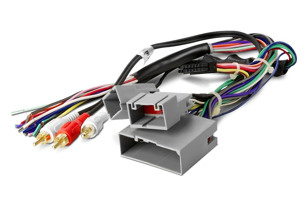
Let's break down the key components. At its core, a car stereo wiring harness is a collection of wires bundled together, terminated with a connector that plugs directly into the back of your head unit (the main stereo unit). These wires carry power, ground, audio signals, and control signals. The ISO 10487 standard defines the connectors and pinout assignments for car radios. While not all cars strictly adhere to this standard, it provides a helpful framework for understanding the general layout.
Main Parts:
- Head Unit Connector: This is the main connector that plugs into the back of your head unit. It contains all the necessary pins for power, ground, speakers, and other functions.
- Power Wires: Usually a thick gauge wire (typically 12-16 AWG) and often red or yellow. This wire supplies the head unit with the necessary power to operate. There are usually two power wires:
- Battery (B+ or Constant 12V): Provides power even when the ignition is off, maintaining memory and settings.
- Ignition (Switched 12V): Provides power only when the ignition is on or in the accessory position.
- Ground Wire: Usually a thick gauge black wire. This provides the return path for the electrical current. A good, solid ground connection is critical for proper operation.
- Speaker Wires: These wires (usually thinner gauge, 18-22 AWG) carry the audio signals to the speakers. There are two wires per speaker: a positive (+) and a negative (-).
- Illumination Wire: Often an orange or orange/white wire. This wire dims the head unit's display when the headlights are turned on.
- Antenna Wire: A single wire (often blue) that connects to the car's antenna. Some newer vehicles might have a separate antenna amplifier power wire (typically blue/white).
- Remote Turn-On Wire (Amplifier Turn-On): A wire (typically blue) that sends a 12V signal to an external amplifier to turn it on when the head unit is powered on.
- Steering Wheel Control Wires: These wires (typically a few thin wires) allow the head unit to be controlled by the steering wheel buttons. These often require a separate adapter module to function correctly.
Understanding Wiring Diagram Symbols
Wiring diagrams use a standardized set of symbols to represent electrical components and connections. Learning these symbols is key to interpreting the diagram. Here's a quick rundown:
- Solid Lines: Represent wires. The thickness of the line doesn't necessarily indicate the wire gauge.
- Dashed Lines: Often represent shielded cables or ground connections.
- Circles: Represent connectors or connection points.
- Squares: Represent components like resistors, capacitors, or diodes.
- Zigzag Lines: Represent resistors.
- Parallel Lines: Represent capacitors.
- Triangles: Often represent diodes or transistors.
- Ground Symbol: Usually a series of horizontal lines, or an inverted triangle, indicating a connection to ground.
- Color Codes: Wires are often color-coded, and these colors are indicated on the diagram using abbreviations (e.g., "R" for red, "BL" for blue, "G" for green, "BK" for black, "W" for white, "Y" for yellow).
- Pin Numbers: Each pin on the connector is numbered, allowing you to identify the function of each wire.
In addition to the standard symbols, wiring diagrams often include notes and labels that provide additional information about the circuit, such as voltage levels, current ratings, and component values.
How It Works: The Flow of Audio
Let's trace the flow of audio through the system. Power from the battery and ignition switch energizes the head unit. The head unit then processes the audio signal (from a CD, radio, Bluetooth, etc.). This processed signal is then sent to the speakers through the speaker wires. A good ground connection ensures a stable return path for the electrical current, preventing noise and distortion. The antenna wire receives the radio signal, which is then processed by the head unit's tuner.
The key is to understand that each wire serves a specific purpose. Treating them with respect and connecting them correctly is essential for a functioning and safe audio system.
Real-World Use: Basic Troubleshooting Tips
Okay, so something's not working. Here's a few common problems and how to use your wiring knowledge to diagnose them:
- No Power to Head Unit: Check the fuses first! Then, use a multimeter to check for 12V at the battery and ignition wires on the harness. Verify the ground connection is solid.
- One Speaker Not Working: Check the speaker wires for that speaker. Make sure they are properly connected to both the head unit and the speaker. Use a multimeter to check for continuity in the speaker wire. A broken wire will show no continuity. Swap the speaker with one that is working to rule out a bad speaker.
- Distorted Audio: Check the speaker wires for shorts to ground. Make sure the speaker impedance matches the head unit's specifications. A loose or corroded ground connection can also cause distortion.
- Head Unit Keeps Resetting: This usually indicates a problem with the constant 12V (battery) wire. Check the fuse and the connection to the battery.
Safety First!
Working with car electrical systems can be dangerous. Always disconnect the negative terminal of the battery before working on any wiring. This prevents accidental shorts and potential damage to the electrical system. Be especially careful when working near airbags or other safety systems. Incorrect wiring can disable these systems. Use proper tools, such as wire strippers, crimpers, and multimeters. Avoid using household tools, as they can damage the wires and connectors. When soldering, use a soldering iron designed for electronics work and be careful not to overheat the components.
Never cut or splice wires without knowing their function. A short circuit can damage your head unit or even start a fire. When in doubt, consult a wiring diagram or a qualified technician.
We've provided you with a solid foundation for understanding car stereo wiring harness connectors. With this knowledge, you'll be better equipped to tackle your next audio upgrade or repair. Remember to always prioritize safety and double-check your work. Happy listening!
And remember, we have a detailed wiring diagram file available for download. It provides a comprehensive overview of common car stereo wiring configurations. This diagram can be a valuable resource when troubleshooting or installing a new stereo system.