Catalytic Converter Location Diagram
Let's talk catalytic converters. These often-overlooked components are crucial for emissions control, and understanding their location and the system they're a part of is essential for anyone tackling more advanced automotive repairs or modifications. This article will dive into catalytic converter location diagrams, explaining their purpose, key components, and how to interpret them. We also have a handy downloadable diagram that you can use for your specific vehicle!
Why a Catalytic Converter Location Diagram Matters
A catalytic converter location diagram isn't just a pretty picture; it's a vital resource for several reasons:
- Repair and Maintenance: Locating the catalytic converter is the first step in diagnosing problems. Issues like reduced engine performance, rattling noises, or failing emissions tests can often be traced back to a faulty converter. The diagram helps you quickly pinpoint its location without unnecessary disassembly.
- Emissions Testing: When your car fails an emissions test, the diagram can guide you through checking the converter for damage or leaks, and understanding the system's overall health.
- Modification and Upgrades: If you're planning exhaust system modifications, such as installing headers or a high-flow exhaust, knowing the precise location and orientation of the catalytic converter is essential for proper fitment and compliance with emissions regulations. (Important note: Modifying or removing a catalytic converter is illegal in many regions. Always check your local laws.)
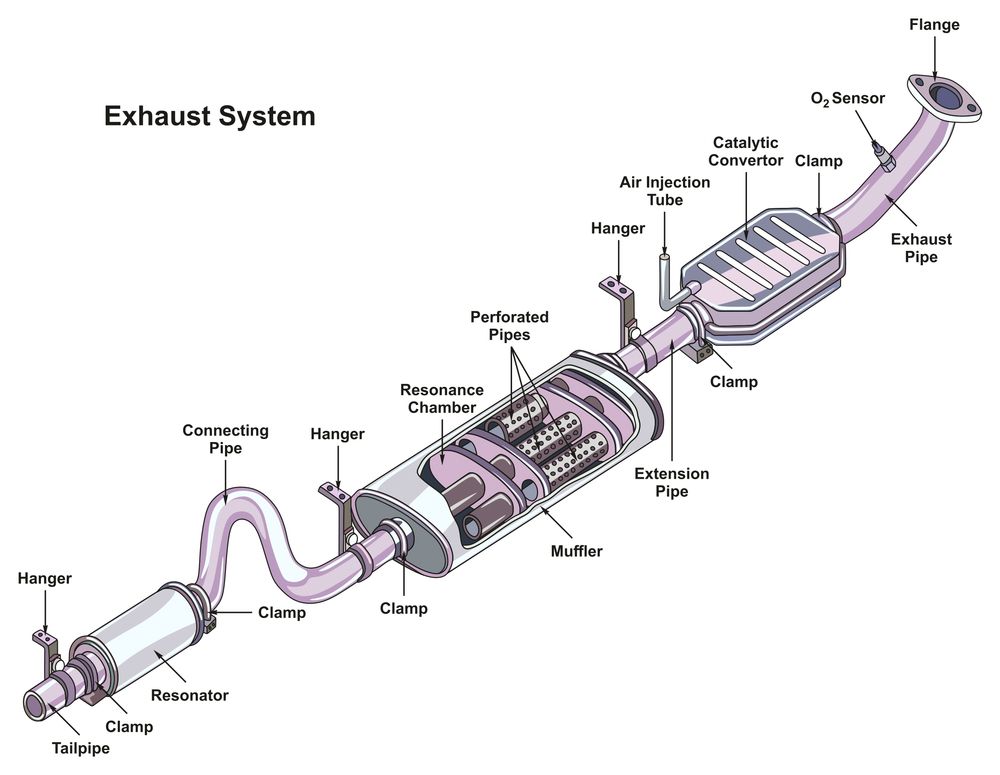
- Understanding the System: The diagram illustrates how the converter integrates with other exhaust system components, like the oxygen sensors (O2 sensors) and exhaust manifolds. This broader understanding is invaluable for troubleshooting and diagnosing related issues.
- Preventative Maintenance: Regularly inspecting the area around the converter, identified using your diagram, helps catch small problems before they escalate into major repairs.
Key Specs and Main Parts Depicted in the Diagram
A typical catalytic converter location diagram will highlight these key specifications and parts:
- Converter Location: The diagram clearly shows the converter's position relative to the engine, exhaust manifold, and other undercarriage components.
- Converter Type: Some diagrams might specify the type of converter used (e.g., three-way converter, diesel oxidation catalyst).
- O2 Sensor Placement: Diagrams always show the locations of the upstream (before the converter) and downstream (after the converter) O2 sensors. These sensors play a critical role in monitoring the converter's efficiency. The O2 sensors provide data to the ECU (Engine Control Unit).
- Exhaust Pipe Routing: The path of the exhaust pipes leading to and from the converter is shown, indicating bends, connections, and mounting points.
- Heat Shields: Heat shields are crucial for protecting surrounding components from the converter's high operating temperatures. The diagram should indicate their location.
- Mounting Points: The diagram will show the bolts, brackets, or hangers used to secure the converter to the vehicle's chassis.
- Part Numbers: In some cases, the diagram might include part numbers for the catalytic converter, O2 sensors, and related hardware.
Understanding the Symbols and Conventions
Diagrams use a standardized set of symbols and conventions to convey information efficiently. Here's a breakdown of common elements:
- Lines: Solid lines typically represent exhaust pipes, while dashed lines might indicate heat shields or other non-structural components.
- Arrows: Arrows show the direction of exhaust flow.
- Colors: Color coding is often used to differentiate between components, such as the exhaust manifold (often depicted in orange or red) and the catalytic converter itself. Some manufacturers use different colors to represent different types of metal or coating used in the exhaust system.
- Icons: Small icons are used to represent O2 sensors, mounting bolts, and other small parts. These icons are usually accompanied by labels for clarity.
- Abbreviations: Expect to see abbreviations like "CAT" for catalytic converter, "O2S" for oxygen sensor, and "EGR" for exhaust gas recirculation (if the EGR system interacts with the exhaust system near the converter).
How a Catalytic Converter Works (The Basics)
A catalytic converter reduces harmful emissions by using a catalyst (usually platinum, palladium, and rhodium) to convert pollutants into less harmful substances. Here's a simplified explanation:
- Exhaust Gas Enters: Exhaust gases from the engine enter the catalytic converter.
- Chemical Reactions: The catalyst promotes chemical reactions that convert carbon monoxide (CO), hydrocarbons (HC), and nitrogen oxides (NOx) into carbon dioxide (CO2), water (H2O), and nitrogen (N2).
- Two-Way vs. Three-Way Converters: Older "two-way" converters primarily address CO and HC. Modern "three-way" converters also tackle NOx.
- Monitoring: O2 sensors upstream and downstream of the converter monitor the exhaust gas composition and provide feedback to the engine control unit (ECU). This feedback loop helps the ECU optimize engine performance and ensure the converter is operating efficiently.
Real-World Use: Basic Troubleshooting
Here are some basic troubleshooting tips using the catalytic converter location diagram:
- Rattling Noise: A rattling noise coming from the undercarriage could indicate a broken or damaged converter. Use the diagram to locate the converter and inspect it for physical damage, such as dents, cracks, or loose internal components.
- Reduced Engine Performance: A clogged catalytic converter can restrict exhaust flow, leading to reduced engine power and fuel economy. Locate the converter using the diagram and check for excessive heat or signs of blockage. (Caution: A very hot converter can be a fire hazard.)
- Failed Emissions Test: If your car fails an emissions test, use the diagram to locate the O2 sensors. Check the O2 sensor readings with a scan tool to see if they are functioning correctly. Faulty O2 sensors can provide inaccurate data, leading to poor converter performance and emissions failures.
- Check Engine Light (CEL): Many diagnostic trouble codes (DTCs) related to the catalytic converter will trigger the CEL. Use a scan tool to retrieve the DTCs and consult the diagram to identify the components involved. For example, a P0420 code (Catalyst System Efficiency Below Threshold) indicates that the converter is not functioning efficiently.
- Visual Inspection: Regularly inspect the converter and its surroundings for signs of damage, leaks, or corrosion. Pay close attention to the heat shields and mounting points.
Safety Considerations
Working around a catalytic converter presents several safety risks:
- High Temperatures: Catalytic converters operate at extremely high temperatures. Never touch a hot converter; allow it to cool completely before working on it. Even after the engine is turned off, the converter can remain hot for a significant period.
- Exhaust Gases: Exhaust gases contain harmful substances, such as carbon monoxide. Always work in a well-ventilated area when working on the exhaust system.
- Burns: Be careful when working near the exhaust system, as the pipes can also be very hot. Wear appropriate protective gear, such as gloves and long sleeves.
- Eye Protection: Wear safety glasses to protect your eyes from debris and particles.
- Jacking and Supporting the Vehicle: Always use proper jacking and support procedures when working under a vehicle. Never work under a vehicle supported only by a jack. Use jack stands to safely support the vehicle.
By understanding catalytic converter location diagrams and following these safety precautions, you can confidently diagnose and repair exhaust system issues, ensuring your vehicle runs efficiently and meets emissions standards. We have a downloadable diagram available that will provide the specific locations for your car. Be sure to consult your vehicles manual for specific instructions.