Central Air Conditioner Wiring Diagram
Understanding the wiring diagram for your central air conditioner is crucial for effective troubleshooting, maintenance, and even safe modifications. Think of it as the electrical roadmap to your cooling system. While a complete overhaul might require professional HVAC technicians, this knowledge empowers you to diagnose common issues, perform basic repairs, and understand the system's operation. We've got a downloadable diagram file that will be a great companion as you learn.
Purpose of the Wiring Diagram
Why bother with a central AC wiring diagram? Several compelling reasons exist:
- Troubleshooting: When your AC malfunctions, the diagram helps you trace the electrical path, identify faulty components, and pinpoint the source of the problem. Is the compressor not starting? Use the diagram to check voltage at key points and isolate the issue to a specific relay, capacitor, or wiring connection.
- Maintenance: Understanding the wiring allows you to perform preventative maintenance more effectively. You can inspect connections for corrosion, check wiring integrity, and ensure proper voltage levels.
- Modifications: If you're considering upgrades like adding a smart thermostat or integrating your AC with a home automation system, the wiring diagram is essential for understanding the existing circuitry and making safe, informed connections.
- Learning: Even if you don't plan on performing extensive repairs, understanding the wiring diagram deepens your knowledge of how the entire system operates. This knowledge is invaluable when communicating with HVAC professionals and understanding their recommendations.
Key Specs and Main Parts
Before diving into the diagram itself, let's define some key components and specifications commonly found in a central air conditioning system:
- Voltage: Typically 220V/240V for the main unit and 24V AC for the control circuit (thermostat). Understanding the voltage requirements is crucial for safe operation and troubleshooting.
- Amperage: Refer to the unit's nameplate for the rated amperage. This is important when selecting replacement components like fuses and circuit breakers.
- Compressor: The heart of the system, responsible for compressing the refrigerant. It draws a significant amount of current.
- Condenser Fan Motor: Cools the condenser coil, which dissipates heat.
- Evaporator Fan Motor: Circulates air across the evaporator coil, absorbing heat from the indoor air.
- Capacitors: Used to start and run the compressor and fan motors. There are typically two types: start capacitors (momentary high voltage boost) and run capacitors (continuous voltage smoothing).
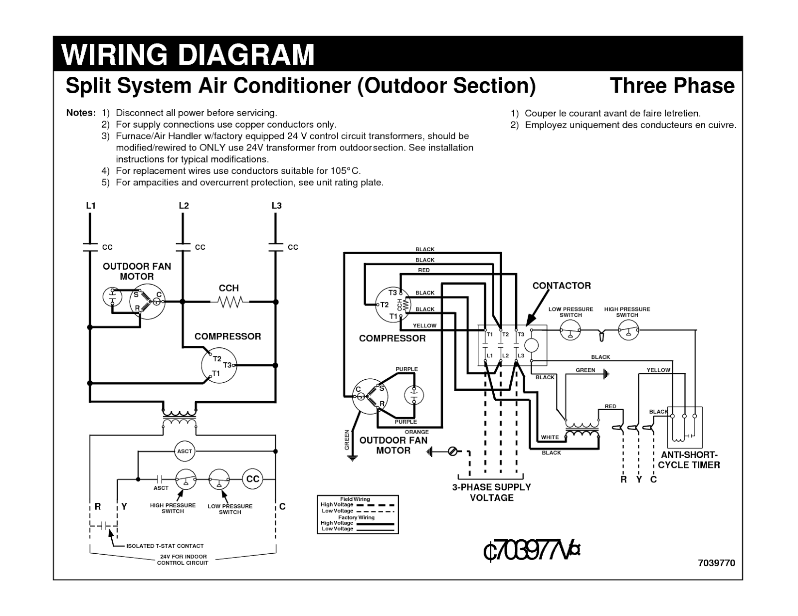
- Contactor: A heavy-duty relay that switches the high-voltage power to the compressor and condenser fan motor. It's controlled by the 24V thermostat circuit.
- Transformer: Steps down the 220V/240V power to 24V for the control circuit.
- Thermostat: Controls the system based on the desired temperature.
- Safety Switches: High-pressure and low-pressure switches protect the compressor from damage due to abnormal operating conditions. There can also be a float switch in the condensate drain pan to shut the unit down if the drain is clogged.
- Fuses/Circuit Breakers: Protect the electrical components from overcurrent.
Symbols: Understanding the Language of the Diagram
Wiring diagrams use a standardized set of symbols to represent electrical components and connections. Here's a breakdown of common symbols:
- Lines: Represent wires. Solid lines typically indicate conductors, while dashed lines might represent shielded cables or control signals. Line thickness generally indicates the conductor size.
- Circles: Can represent various components. Filled circles often indicate wire connections. Unfilled circles with a symbol inside represent components like resistors, capacitors, or inductors.
- Rectangles: Typically represent components like relays, transformers, and control modules.
- Switches: Represented by a line segment connected to a pivot point. The position of the line indicates the switch's state (open or closed).
- Ground Symbol: A series of horizontal lines decreasing in length, indicating a connection to the earth ground.
- Colors: Wires are often color-coded to aid in identification. Common colors include black (hot), white (neutral), green (ground), red (control signals), and blue (control signals). The specific color code can vary depending on the manufacturer and region, but you’ll usually find a legend on the diagram.
- Component Labels: Each component is typically labeled with a unique identifier (e.g., C for capacitor, R for relay, T for transformer). These labels correspond to a parts list or other documentation that provides more detailed information about the component.
How It Works: A Simplified Explanation
Here's a simplified overview of how a central AC system's electrical system typically operates:
- The thermostat calls for cooling, sending a 24V AC signal to the contactor coil.
- The energized contactor pulls in, closing the high-voltage contacts.
- This connects the 220V/240V power to the compressor and condenser fan motor, starting them.
- The compressor circulates refrigerant through the system, while the condenser fan motor cools the condenser coil.
- The evaporator fan motor circulates air across the evaporator coil, absorbing heat from the indoor air.
- When the thermostat reaches the desired temperature, it de-energizes the contactor, shutting off the compressor and condenser fan motor. The evaporator fan might continue to run depending on the system.
- Safety switches monitor the system's pressure and temperature, shutting down the compressor if abnormal conditions are detected.
This is a highly simplified explanation; the actual operation can be more complex, depending on the specific system design.
Real-World Use: Basic Troubleshooting Tips
Now, let's explore some basic troubleshooting scenarios where the wiring diagram can be your best friend:
- AC not turning on:
- Check the circuit breaker.
- Verify that the thermostat is set correctly and the batteries are good.
- Use the diagram to trace the 24V signal from the thermostat to the contactor. If there's no voltage at the contactor coil, there's a problem in the control circuit (e.g., faulty thermostat, broken wire, blown fuse in the control circuit, tripped safety switch).
- If there is voltage at the contactor coil but the compressor isn't starting, the contactor itself may be faulty. Use a multimeter to check the continuity of the high-voltage contacts when the contactor is energized.
- Fan not running:
- Check the capacitor associated with the fan motor. A bulging or leaking capacitor is a common sign of failure.
- Use the diagram to trace the power to the fan motor and check for voltage.
- Check the motor windings for continuity with a multimeter.
- Compressor not starting:
- Check the capacitor associated with the compressor.
- Verify that the contactor is working properly.
- Check the compressor's internal overload protector (if equipped).
Remember to always disconnect power before working on any electrical components. Use your wiring diagram to guide your diagnostics and always double-check your work.
Safety: Handle with Care
Working with electrical systems can be dangerous. Exercise extreme caution and always follow these safety precautions:
- Disconnect Power: Before working on any electrical components, always disconnect the power at the main circuit breaker. Verify that the power is off using a multimeter.
- High Voltage: The 220V/240V components (compressor, condenser fan motor, contactor) are potentially lethal. Avoid contact with these components when the power is on.
- Capacitors: Capacitors can store a charge even after the power is disconnected. Discharge capacitors before handling them to avoid electric shock. You can safely discharge them with a resistor.
- Proper Tools: Use insulated tools designed for electrical work.
- Qualified Technician: If you're not comfortable working with electrical systems, or if you encounter complex problems, consult a qualified HVAC technician.
Working with refrigerant also carries risks. Only a licensed professional should handle refrigerant.
We have the central air conditioner wiring diagram file ready for you to download. It will be a valuable resource as you learn more about your AC system. Understanding the wiring diagram is the first step towards becoming a more informed and capable homeowner when it comes to your home's cooling system.