
Chevy 1 Wire Alternator Wiring Diagram
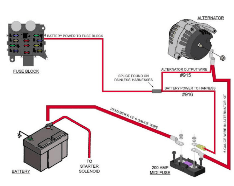
Alright, let's talk about the Chevy 1-Wire Alternator Wiring Diagram. You're probably here because you're either dealing with alternator issues, upgrading to a simpler system, or just diving deeper into the electrical guts of your ride. Understanding this diagram is crucial for troubleshooting, repairs, and modifications, especially when dealing with older vehicles or custom builds. I'll break it down into manageable chunks, so you can confidently navigate the world of 1-wire alternators.
Purpose and Why You Need This Diagram
The primary purpose of a wiring diagram is to provide a visual representation of the electrical connections within a system. Specifically, the 1-wire alternator diagram helps you understand how the alternator is wired in a simplified setup. This is especially helpful when:
- Converting from an external voltage regulator to a self-exciting alternator: Many older vehicles used external voltage regulators. A 1-wire alternator eliminates this component, streamlining the wiring.
- Troubleshooting charging issues: If your battery isn't charging correctly, the diagram helps you trace the wiring and identify potential problems like loose connections or faulty components.
- Custom Builds or Swaps: When working on a custom car, hot rod, or engine swap, using a 1-wire alternator simplifies the wiring process and reduces clutter.
- Learning Electrical Systems: Even if you're not actively working on your car, understanding this diagram provides a foundational understanding of basic automotive electrical systems.
Having the correct diagram is *essential* before you start poking around with electrical components, or you risk doing more harm than good.
Key Specs and Main Parts
Before we dissect the diagram, let's identify the key components involved in a 1-wire alternator system:
- Alternator: The heart of the charging system, converting mechanical energy from the engine into electrical energy to charge the battery and power electrical accessories. Key specs include its amperage output (e.g., 63 amp, 100 amp, etc.) and its "1-wire" configuration, meaning it doesn't require a separate excitation wire.
- Battery: Stores electrical energy and provides power to start the engine and run accessories when the alternator isn't producing enough power. Pay attention to battery Voltage requirements of 12V.
- Main Power Wire (Charge Wire): This heavy-gauge wire carries the current from the alternator to the battery. It's the "1 wire" that gives the alternator its name.
- Fuse or Fusible Link: A safety device placed in the main power wire to protect the electrical system from overcurrent. It's designed to melt and break the circuit if the current exceeds a certain level.
- Ground Wire: Provides a return path for the electrical current back to the battery. Proper grounding is crucial for the entire system to function correctly.
Symbols – Decoding the Diagram
A wiring diagram is a roadmap of electrical connections. Understanding the symbols is crucial for navigating it:
- Solid Lines: Represent wires. Thicker lines generally indicate wires carrying higher current.
- Dashed Lines: Often represent shielding or optional connections.
- Circles: Can represent various components, sometimes with letters inside indicating what component they refer to (e.g., "ALT" for alternator).
- Rectangles: Often represent switches, relays, or control modules.
- Resistor Symbol (Zig-zag line): Represents a resistor, which limits current flow.
- Ground Symbol (Stacked horizontal lines): Indicates a connection to ground, which is typically the vehicle's chassis.
- Fuse Symbol: Usually looks like a small, squiggly line enclosed in a rectangle or a simple line break symbol.
Color Coding: Wiring diagrams often use color codes to identify wires. Common colors include:
- Red: Typically indicates a positive (+) power wire.
- Black: Typically indicates a ground (-) wire.
- Other Colors: May represent wires for specific functions, such as indicator lights or control signals. Consult the diagram's legend for specific color designations.
How It Works – The 1-Wire Magic
The beauty of the 1-wire alternator lies in its simplicity. Here's the basic principle:
- Engine Start: When the engine starts, the alternator begins to spin.
- Self-Excitation: Unlike traditional alternators that require an external voltage regulator to "excite" the field windings (the coils that create the magnetic field), a 1-wire alternator is designed to self-excite. This means that as it spins, it generates a small amount of voltage internally.
- Voltage Build-Up: This small voltage is enough to start the excitation process. As the field windings are energized, the alternator produces more voltage.
- Charging: The alternator's output voltage increases until it reaches the specified charging voltage (typically around 13.8-14.4 volts). This voltage is then sent through the main power wire to the battery, charging it and powering the vehicle's electrical system.
- Voltage Regulation: The 1-wire alternator contains an internal voltage regulator that automatically maintains the correct charging voltage, preventing overcharging and damage to the battery.
In essence, it eliminates the need for a separate excitation wire running from the ignition switch or voltage regulator to the alternator. That’s why it's called “1-wire”.
Real-World Use – Basic Troubleshooting
Okay, let’s say you think something’s up with your charging system. Here's how a 1-wire alternator wiring diagram can help you troubleshoot:
- No Charging: If the battery isn't charging, the first step is to check the main power wire connection at both the alternator and the battery. Make sure the connections are clean and tight. Also, check the fuse or fusible link in the main power wire. If it's blown, replace it with one of the correct amperage rating. Use a multimeter to check the output voltage of the alternator while the engine is running. It should be in the range of 13.8-14.4 volts. If it's significantly lower or higher, the alternator may be faulty.
- Overcharging: If the battery is constantly overcharging, the internal voltage regulator in the alternator is likely failing. You'll probably need to replace the entire alternator.
- Erratic Charging: Intermittent charging issues can be caused by loose connections, corroded terminals, or a faulty alternator. Carefully inspect all wiring connections and terminals.
Grounding Issues:Always ensure proper grounding. A bad ground connection can cause all sorts of electrical problems. Clean the grounding points and ensure they are securely connected to the vehicle's chassis.
Safety – Respect the Electricity!
Working with automotive electrical systems can be dangerous if you're not careful. Here are some essential safety precautions:
- Disconnect the Battery: Always disconnect the negative (-) battery cable before working on any electrical components. This prevents accidental short circuits.
- Wear Safety Glasses: Protect your eyes from sparks and debris.
- Use Insulated Tools: Use tools with insulated handles to prevent electrical shock.
- Avoid Working in Wet Conditions: Water conducts electricity, increasing the risk of shock.
- Be Mindful of the Alternator: Even after disconnecting the battery, the alternator can retain a small amount of residual charge. Avoid touching the terminals after disconnecting the battery.
- Fuses and Fusible Links: Never bypass a fuse or fusible link. These are safety devices designed to protect the electrical system. Replacing a blown fuse with a higher amperage fuse is also extremely dangerous and can cause a fire.
Working on the electrical system presents significant risks. Specifically, capacitors within the alternator can hold a dangerous charge, even after the car is off. Respect this. If you’re not comfortable working with electricity, seek the help of a qualified mechanic.
You now have a solid understanding of the Chevy 1-Wire Alternator Wiring Diagram. Remember to always refer to your specific vehicle's service manual for detailed instructions and safety precautions. Keep learning and be safe out there!