
Chevy 3 Wire Alternator Wiring Diagram
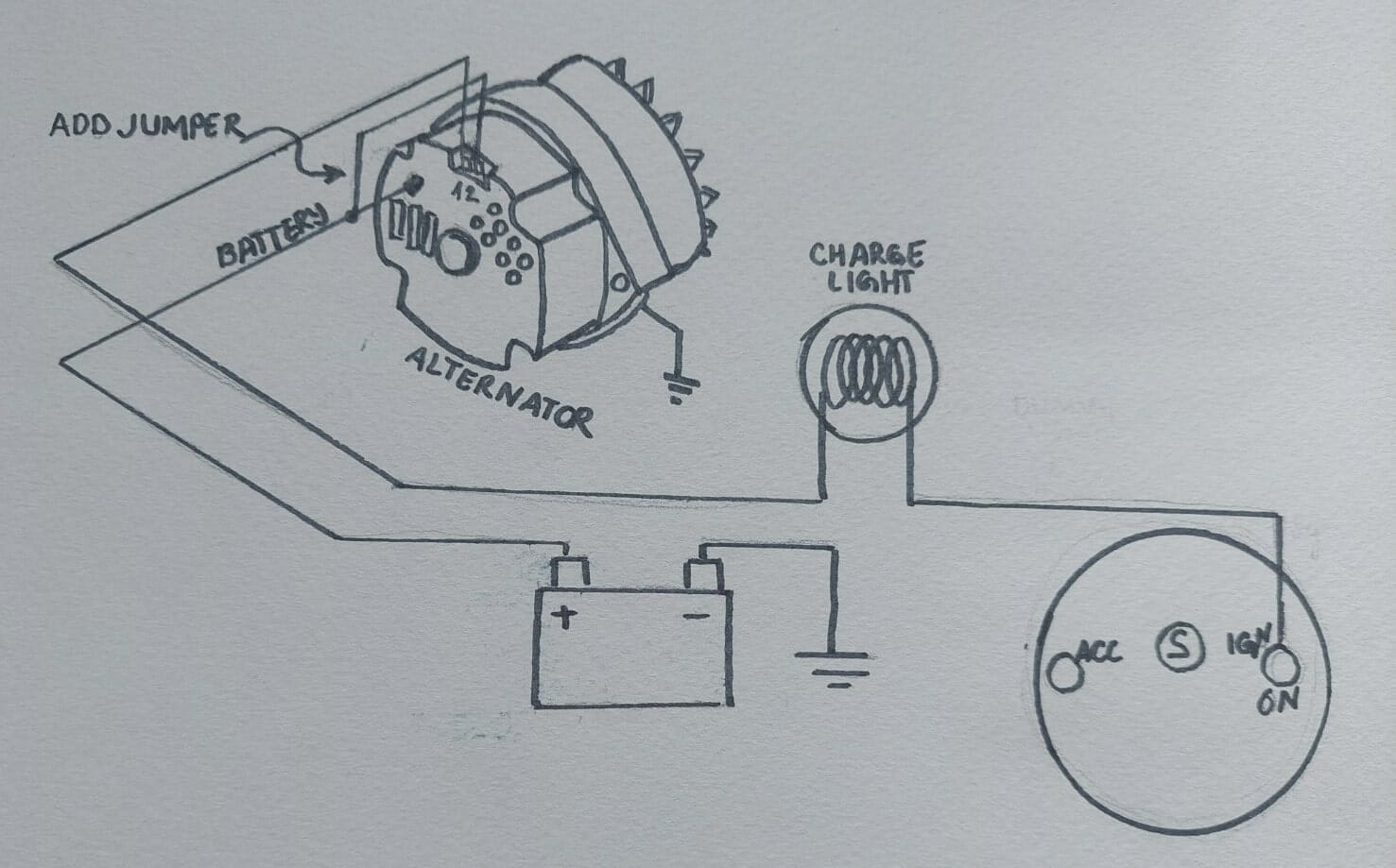
The venerable Chevy 3-wire alternator is a staple in automotive electrical systems, finding its way into countless classic cars, trucks, and even custom builds. Understanding its wiring diagram is crucial for troubleshooting charging issues, performing upgrades, or even for understanding the basics of alternator operation. This article will break down the 3-wire alternator wiring diagram, providing you with the knowledge to confidently diagnose and repair related problems.
Purpose of Understanding the 3-Wire Alternator Wiring Diagram
Why should you care about this wiring diagram? Several reasons:
- Troubleshooting: If your battery isn't charging properly, or your voltage gauge is acting erratically, understanding the wiring allows you to pinpoint the problem's source – is it the alternator itself, the wiring, or another component?
- Upgrades/Modifications: Swapping an older generator for a more modern alternator (like a 3-wire) is a common upgrade. Knowing the wiring is essential for a safe and functional installation.
- Understanding Automotive Electrical Systems: Even if you don't plan on working on your charging system immediately, comprehending the 3-wire alternator's operation provides a valuable foundation for understanding how automotive electrical systems function.
Key Specs and Main Parts
Before diving into the diagram, let's define the key components:
- Alternator: The core of the charging system, converting mechanical energy from the engine into electrical energy. Its internal components include a rotor, stator, diodes, and a voltage regulator.
- Battery: Stores electrical energy and provides the initial power to start the engine. It also acts as a buffer to stabilize the electrical system.
- Voltage Regulator: Crucial for maintaining a consistent voltage output from the alternator (typically around 13.8-14.7 volts). It controls the amount of current flowing through the rotor (field windings) inside the alternator.
- Wiring Harness: The bundle of wires connecting the various components of the charging system.
- Fuses/Fusible Links: Safety devices that protect the electrical system from overcurrents.
- Ammeter/Voltmeter: Gauges that display the charging system's current flow (ammeter) or voltage output (voltmeter).
The "3-wire" designation refers to the three essential wires connected to the alternator:
- BAT (Battery) or Output Terminal: The heavy-gauge wire that connects directly to the positive (+) terminal of the battery (or a distribution block connected to the battery). This carries the charging current to the battery and powers the vehicle's electrical system.
- S (Sense) Terminal: This smaller-gauge wire senses the voltage at a distant point in the electrical system, typically near the battery or at the main power distribution block. This allows the voltage regulator to compensate for voltage drop in the wiring, ensuring the battery receives the correct charging voltage.
- I (Ignition) Terminal: This smaller-gauge wire receives power from the ignition switch when the engine is running (in the "Run" or "On" position). This provides the initial excitation current to the alternator's field windings, allowing it to start charging.
Symbols and Color Coding in the Wiring Diagram
Understanding the symbols and conventions used in wiring diagrams is critical for interpreting them correctly. Here's a breakdown:
- Lines: Lines represent wires. Thicker lines usually indicate wires carrying higher current loads (like the BAT wire).
- Colors: Wire colors are standardized to some extent, but can vary between manufacturers and models. Common colors include:
- Red: Typically used for battery power and main power distribution.
- Black: Typically used for ground connections.
- Orange/Yellow: Often used for ignition-switched power.
- Blue/Green: Can be used for various functions, often related to sensors or control signals.
- Ground Symbol: Looks like an upside-down triangle or a series of horizontal lines. This indicates a connection to the vehicle's chassis, which serves as the return path for the electrical circuit.
- Fuse Symbol: A wavy line inside a rectangle or a simple line break. Indicates the presence of a fuse or fusible link.
- Component Symbols: Each electrical component (alternator, battery, ignition switch, etc.) has its own specific symbol. You'll find guides online showing common electronic symbols if unfamiliar.
A typical 3-wire alternator wiring diagram might show the BAT wire as a thick red line, the S wire as a thin orange line, and the I wire as a thin blue line.
How It Works: The Charging Cycle
Here's how the 3-wire alternator works to keep your battery charged:
- Initial Excitation: When you turn the ignition switch to the "Run" position, power flows through the I terminal to the alternator's voltage regulator. This excites the field windings, creating a small magnetic field.
- Rotor Rotation and Stator Induction: As the engine starts, the alternator's rotor spins. The rotating magnetic field from the rotor induces a current in the stator windings.
- Rectification: The stator windings generate alternating current (AC). Diodes inside the alternator rectify this AC into direct current (DC), which is suitable for charging the battery and powering the vehicle's electrical system.
- Voltage Regulation: The voltage regulator constantly monitors the voltage at the S terminal (the "sense" wire). If the voltage drops below the setpoint (e.g., 14.2 volts), the regulator increases the current flowing through the rotor's field windings, increasing the alternator's output. If the voltage rises above the setpoint, the regulator decreases the current, reducing the alternator's output.
- Battery Charging: The DC current from the alternator flows through the BAT wire to the battery, replenishing its charge.
The "sense" wire (S terminal) is particularly important. It provides feedback to the voltage regulator, allowing it to compensate for voltage drop caused by resistance in the wiring between the alternator and the battery. Without this sense wire, the battery might not receive a full charge, or the alternator could overcharge the battery.
Real-World Use: Basic Troubleshooting Tips
Here are some common issues and how to troubleshoot them using your knowledge of the 3-wire alternator wiring diagram:
- Battery Not Charging:
- Check the BAT wire connection: Ensure it's clean, tight, and free of corrosion. Use a multimeter to verify that voltage is present at the BAT terminal when the engine is running. If no voltage is present, check the wiring between the alternator and the battery, including any fuses or fusible links.
- Check the I wire connection: Verify that the I wire receives power when the ignition is in the "Run" position. If not, trace the wire back to the ignition switch and check for continuity.
- Check the S wire connection: Make sure the S wire is properly connected to a point in the electrical system that accurately reflects the battery voltage. A poor connection here can lead to undercharging or overcharging.
- Test the Alternator: A failing alternator may have internal faults. Many auto parts stores offer free alternator testing.
- Overcharging:
- Check the S wire connection: An open or disconnected S wire can cause the alternator to output maximum voltage, leading to overcharging.
- Check the Voltage Regulator: A faulty voltage regulator can also cause overcharging. Replacement is often necessary if the regulator is integrated into the alternator.
- Erratic Voltage Gauge Readings:
- Check all connections: Loose or corroded connections can cause fluctuating voltage readings.
- Check Ground Connections: A poor ground connection for the alternator or voltage regulator can also cause erratic readings. Ensure all ground straps and wires are clean and tightly secured.
A good tool for troubleshooting is a multimeter. Use it to check voltage, continuity, and resistance in the wiring. A test light can also be helpful for quickly checking for the presence of voltage.
Safety Precautions
Working with automotive electrical systems can be dangerous. Always observe the following safety precautions:
- Disconnect the Battery: Before working on any electrical components, disconnect the negative (-) terminal of the battery. This will prevent accidental short circuits and potential electrical shock.
- Wear Safety Glasses: Protect your eyes from debris and battery acid.
- Use Insulated Tools: Use tools with insulated handles to reduce the risk of electrical shock.
- Avoid Working in Wet Conditions: Water conducts electricity, increasing the risk of electrical shock.
- Be Careful Around the Alternator Pulley: When the engine is running, the alternator pulley is spinning rapidly. Keep your hands and clothing clear of the pulley and belt.
- Handle Battery Acid with Care: Battery acid is corrosive and can cause burns. Wear gloves and eye protection when handling batteries.
The BAT terminal on the alternator carries significant current and voltage. Accidental shorts to ground from this terminal can cause damage to the alternator, wiring, and battery, and can even start a fire. Always disconnect the battery before working on the BAT wire.
This article provides a comprehensive overview of the Chevy 3-wire alternator wiring diagram. Understanding this diagram empowers you to diagnose charging system problems, perform upgrades, and expand your automotive electrical knowledge.