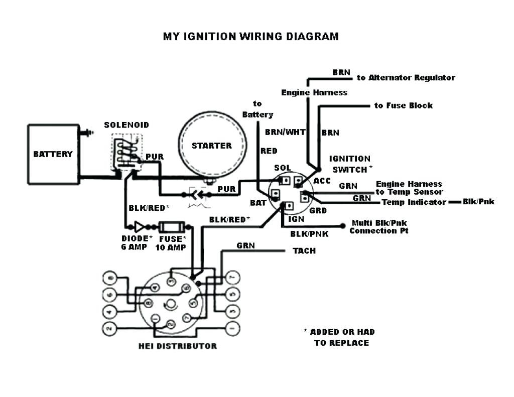
Chevy 350 Distributor Wiring Diagram
The venerable Chevy 350 small-block engine. A legend in its own right. Whether you're restoring a classic, hot-rodding a project car, or simply maintaining your daily driver, understanding the 350's distributor wiring is crucial. This guide provides a detailed breakdown of the wiring diagram, empowering you to diagnose issues, perform repairs, and even upgrade your ignition system with confidence. We're assuming you're comfortable with basic automotive electrical concepts and tools. This isn't for complete beginners, but we'll aim for clarity.
Purpose of Understanding the 350 Distributor Wiring Diagram
Why bother learning about this intricate web of wires? Several reasons spring to mind:
- Troubleshooting Ignition Problems: A faulty distributor or its wiring can cause a no-start condition, misfires, or poor engine performance. A wiring diagram helps you pinpoint the source of the problem.
- Performance Upgrades: Upgrading to an aftermarket ignition system (like HEI or electronic ignition) requires understanding the existing wiring to ensure proper installation and compatibility.
- Restoration Projects: Correctly wiring the distributor is essential for a faithful restoration of a classic Chevy.
- Learning Engine Basics: Studying the distributor wiring provides valuable insight into how the ignition system functions and its role in the combustion process.
- Avoiding Costly Repairs: Being able to diagnose and fix minor wiring issues yourself can save you a significant amount of money at the mechanic's shop.
Key Specs and Main Parts of the 350 Distributor
Before diving into the wiring, let's identify the key components of a typical 350 distributor:
- Distributor Housing: The main body of the distributor, usually made of cast aluminum.
- Distributor Cap: A removable cap with terminals that direct the high-voltage spark to the correct cylinder.
- Rotor: A rotating arm inside the distributor cap that connects to the coil and distributes the spark.
- Pick-up Coil (Magnetic Pick-up): Generates a signal that triggers the ignition module to fire the coil. In older points-type distributors, this is replaced by the points and condenser.
- Ignition Module: An electronic component that controls the ignition coil's firing based on the signal from the pick-up coil. (Note: Not always located inside the distributor, especially in older systems).
- Vacuum Advance Unit: A diaphragm-operated unit that advances the ignition timing based on engine vacuum, improving fuel economy and driveability.
- Mechanical Advance Weights and Springs: A mechanical system that advances the ignition timing based on engine RPM.
- Ignition Coil: An inductive coil that generates the high-voltage spark needed to ignite the air-fuel mixture. The coil may be located externally or built into the distributor (like in an HEI system).
- Primary Wiring: Low-voltage wiring that connects the distributor to the ignition switch and other components.
- Secondary Wiring: High-voltage wiring (spark plug wires) that connects the distributor cap to the spark plugs.
For specifications, refer to your specific engine and distributor model. Critical specs include: dwell angle (for points systems), timing advance curves (mechanical and vacuum), and voltage requirements of the ignition module and coil.
Symbols and Conventions in a Distributor Wiring Diagram
Wiring diagrams use standard symbols to represent electrical components and connections. Understanding these symbols is essential for interpreting the diagram.
- Solid Lines: Represent wires. The thickness of the line does *not* generally indicate wire gauge.
- Dotted Lines: May represent ground connections, or occasionally, shielded wires. Check the diagram's legend.
- Circles: Often represent connectors or junctions where wires are joined.
- Rectangles: Typically represent electrical components like relays, fuses, or the ignition module.
- Resistor Symbol (Zig-zag line): Represents a resistor. Some older systems use a ballast resistor to reduce voltage to the coil after starting.
- Ground Symbol: Indicates a connection to the vehicle's chassis ground.
Color Coding: Color coding is crucial. Wiring diagrams typically indicate the wire color with abbreviations (e.g., RED, BLK, WHT, GRN). Always verify the wire color on your vehicle matches the diagram. Common colors include:
- Red: Often used for power (e.g., battery voltage).
- Black: Usually indicates ground.
- White: May be used for sensor signals or ignition signals.
- Green: Often used for ground connections.
Wire Gauge: The wiring diagram may or may not indicate wire gauge. If it does, it will usually be indicated next to the wire line (e.g., 16 GA). Use appropriately sized wire for replacements; using too small of a gauge can cause overheating and voltage drop.
How the 350 Distributor Wiring Works
The 350 distributor's primary function is to trigger the ignition coil to fire at the precise moment to ignite the air-fuel mixture in each cylinder. Here's a simplified explanation:
- Power Supply: The ignition switch provides power to the ignition coil and the ignition module (or points, in older systems).
- Pick-up Coil Activation: As the distributor shaft rotates, the pick-up coil (or points) generates a signal when a reluctor tooth (or the points lobe) passes by.
- Ignition Module Triggering: The signal from the pick-up coil (or points) triggers the ignition module to interrupt the current flow to the ignition coil.
- Coil Discharge: When the current flow to the ignition coil is interrupted, the magnetic field in the coil collapses rapidly. This induces a very high voltage in the secondary winding of the coil.
- Spark Distribution: The high-voltage spark travels from the coil to the center terminal of the distributor cap. The rotor, which is synchronized with the engine's crankshaft, distributes the spark to the correct cylinder terminal in the distributor cap.
- Spark Plug Ignition: The high-voltage spark travels through the spark plug wire to the spark plug, where it jumps the gap and ignites the air-fuel mixture in the cylinder.
- Timing Advance: The vacuum advance and mechanical advance mechanisms adjust the timing of the spark based on engine load and RPM, optimizing engine performance and fuel efficiency.
In older points-type distributors, the points serve as a mechanical switch to interrupt the current flow to the coil. The condenser (capacitor) is connected in parallel with the points to prevent arcing and extend their lifespan.
Real-World Use and Basic Troubleshooting
Here's how you can use a 350 distributor wiring diagram for troubleshooting:
- No Start: Use a multimeter to check for voltage at the ignition coil positive terminal with the ignition switch in the "ON" position. If there's no voltage, check the wiring and fuse between the ignition switch and the coil. Also, check the ground connection for the coil.
- Misfire: A misfire can be caused by faulty spark plugs, wires, or a problem within the distributor. Inspect the distributor cap and rotor for cracks, corrosion, or damage. Check the resistance of the spark plug wires. Use a timing light to verify the ignition timing is correct.
- Poor Performance: Check the vacuum advance unit for proper operation. Disconnect the vacuum hose from the distributor and suck on the hose. The timing should advance when vacuum is applied. Inspect the mechanical advance weights and springs for wear or breakage.
- Continuity Testing: Use a multimeter to test the continuity of wires in the distributor circuit. This will help you identify broken or shorted wires. Disconnect the battery before performing continuity tests.
Example: Let's say your Chevy 350 won't start. You consult the wiring diagram and identify the wire that provides power to the ignition module. You use a multimeter to check for voltage at that wire when the ignition is switched on. If there's no voltage, you know the problem lies upstream of that point (e.g., a blown fuse, a faulty ignition switch, or a broken wire). If there *is* voltage, the problem likely lies within the distributor itself (e.g., a faulty ignition module, a broken pick-up coil, or a damaged rotor).
Safety Precautions
Working with automotive electrical systems can be dangerous. Always follow these safety precautions:
- Disconnect the Battery: Always disconnect the negative battery cable before working on any electrical components. This will prevent accidental shorts and shocks.
- High-Voltage Components: Be extremely careful when working with the ignition coil and spark plug wires. These components carry very high voltage and can deliver a dangerous shock, even after the engine is turned off. Use insulated tools and avoid touching these components when the ignition is on.
- Fuel Lines: Be aware of the proximity of fuel lines to the distributor. Avoid creating sparks near fuel lines, as this could cause a fire.
- Proper Tools: Use the correct tools for the job, including insulated pliers, screwdrivers, and a multimeter.
- Consult a Professional: If you are not comfortable working with electrical systems, consult a qualified mechanic.
Always double-check your work and consult a repair manual specific to your vehicle. Incorrect wiring can damage electrical components and even cause a fire.
Remember that wiring diagrams can vary slightly depending on the year and model of your Chevy 350. If you're working on an unusual setup (e.g., a custom engine swap), you may need to create your own wiring diagram based on the specific components you're using.
We have a downloadable version of a typical Chevy 350 distributor wiring diagram available. With this resource and the knowledge you've gained from this article, you'll be well-equipped to tackle any distributor wiring project.