
Chevy 5.7 Vortec Firing Order Diagram
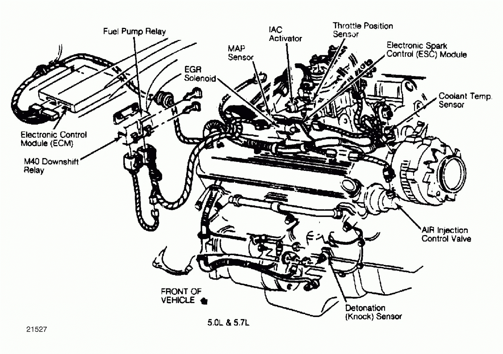
Understanding the firing order of your Chevy 5.7 Vortec engine is crucial for a variety of maintenance and repair tasks. This isn't just about randomly connecting spark plug wires; it's about ensuring the engine operates smoothly, efficiently, and without damaging consequences. A correct firing order guarantees that each cylinder receives the spark at the precise moment needed for optimal combustion. This article will delve into the intricacies of the 5.7 Vortec firing order diagram, equipping you with the knowledge to diagnose issues, perform maintenance, and even undertake performance modifications with confidence.
Purpose of the Firing Order Diagram
The firing order diagram is your roadmap to the engine's ignition timing. Its primary purposes include:
- Diagnosis: Identifying misfires, rough idling, and other performance issues often starts with verifying the firing order. Incorrectly placed spark plug wires can lead to serious engine damage.
- Maintenance: When replacing spark plugs, wires, distributor caps, or performing other ignition-related maintenance, the diagram ensures accurate reassembly.
- Performance Tuning: Modifying the ignition system or engine components requires a thorough understanding of the firing order to optimize performance.
- Educational Value: Learning the firing order provides a deeper understanding of internal combustion engine operation.
Key Specs and Main Parts
The Chevy 5.7 Vortec, a staple in GM trucks and SUVs from the mid-1990s to the early 2000s, has a specific firing order that must be followed. The key specification is:
Firing Order: 1-8-4-3-6-5-7-2
This sequence dictates the order in which the cylinders ignite during each engine cycle. Understanding the cylinder numbering is equally important. When standing in front of the engine, facing the engine bay (assuming a standard North American engine layout):
- Left Bank (Driver's Side): Cylinders 1, 3, 5, and 7
- Right Bank (Passenger's Side): Cylinders 2, 4, 6, and 8
From front to back, the cylinders are numbered sequentially on each bank. The main components involved in the ignition system that are relevant to the firing order include:
- Distributor: The distributor rotor rotates and distributes the high-voltage spark to the correct cylinder based on the firing order. Older Vortec engines use a physical distributor.
- Distributor Cap: The distributor cap houses terminals that correspond to each cylinder. Spark plug wires connect these terminals to the spark plugs.
- Spark Plug Wires: These wires carry the high-voltage electricity from the distributor cap to the spark plugs.
- Spark Plugs: Located in each cylinder, spark plugs ignite the air-fuel mixture, initiating combustion.
- Ignition Coil: Provides the high voltage needed to create a spark.
- Crankshaft Position Sensor (CKP): This sensor provides information to the PCM about the position and rotational speed of the crankshaft. This is particularly important for distributor-less ignition systems.
- Camshaft Position Sensor (CMP): Provides information about the position of the camshaft, helping the PCM determine which cylinder is ready to fire. Only relevant to distributor-less systems.
- PCM (Powertrain Control Module): On distributor-less systems, the PCM controls when each coil fires, based on information from the CKP and CMP sensors.
Symbols in the Firing Order Diagram
A typical firing order diagram uses specific symbols to represent components and connections. While the exact representation may vary slightly depending on the source, common elements include:
- Cylinders: Numbered circles or rectangles representing each cylinder.
- Distributor Cap Terminals: Numbered points on the distributor cap, corresponding to the cylinder numbers.
- Lines: Solid lines connecting the distributor cap terminals to the corresponding cylinders, illustrating the path of the spark. The length of the line does NOT correspond to the length of the wire.
- Arrows: Indicate the direction of distributor rotor rotation.
- Colors: Colors can be used to differentiate between banks (left and right) or to highlight specific connections. The colors themselves are not standardized, so a key is essential.
- Icons: Small icons might represent the spark plugs or other components.
It's crucial to understand the legend or key accompanying the diagram to accurately interpret the symbols used.
How It Works
The firing order is intrinsically linked to the engine's 4-stroke cycle (Intake, Compression, Combustion, Exhaust). The crankshaft rotates twice for each complete cycle. The distributor (or PCM in distributor-less systems) ensures that each cylinder receives a spark at the precise moment of peak compression. The camshaft, synchronized with the crankshaft, controls the opening and closing of the valves, further coordinating the timing of the engine cycle.
In a distributor-equipped system, as the distributor rotor spins, it aligns with each terminal on the distributor cap in sequence. This completes the circuit, allowing the high-voltage electricity from the coil to jump the gap at the spark plug, igniting the air-fuel mixture. The firing order (1-8-4-3-6-5-7-2) dictates this sequential firing.
In a distributor-less system, also known as coil-on-plug (COP) or coil-near-plug, the PCM uses information from the crankshaft and camshaft position sensors to determine the exact moment to fire each individual coil. This eliminates the need for a distributor and can offer more precise ignition timing. The underlying principle of the firing order remains the same, but the control mechanism is electronic rather than mechanical.
Real-World Use – Basic Troubleshooting Tips
Here are some common troubleshooting scenarios where understanding the firing order is essential:
- Misfire: If a cylinder isn't firing correctly, causing a misfire, use the firing order diagram to check if the spark plug wire is connected to the correct cylinder. A P030X code (where X is the cylinder number) will point you to the specific cylinder with the misfire.
- Rough Idle: A rough idle can be caused by incorrect spark plug wire placement. Double-check the firing order against the diagram.
- Engine Knock: An engine knock (detonation or pre-ignition) can sometimes be triggered by incorrect ignition timing due to wiring errors.
- After Replacing Spark Plugs/Wires: Always verify the firing order after replacing these components to ensure correct installation.
Example: Let's say you're experiencing a misfire on cylinder #3. You'd first confirm that the spark plug wire connected to cylinder #3 is properly attached to both the spark plug and the correct terminal on the distributor cap (or the correct coil in a distributor-less system). Use the firing order diagram to trace the wire back and ensure it corresponds to the cylinder number.
Common Mistake: A frequent mistake is confusing the cylinder numbers on each bank. Remember, the cylinder numbers increase from front to back on each side of the engine. Double-check your work, especially if you're working in a cramped engine bay.
Safety – Highlight Risky Components
Working with the ignition system involves high voltage, which can be dangerous. Follow these safety precautions:
- Disconnect the Battery: Always disconnect the negative battery terminal before working on the ignition system to prevent electrical shock.
- Avoid Touching Live Wires: Never touch spark plug wires while the engine is running or the ignition is on. The voltage is extremely high and can be lethal.
- Use Insulated Tools: Use insulated tools when working near electrical components.
- Work in a Well-Ventilated Area: When dealing with gasoline or other flammable fluids, work in a well-ventilated area to avoid the risk of fire or explosion.
- Distributor Cap Precautions: If your engine has a distributor, be aware that the internal components can retain a static charge even after the battery is disconnected. Handle with care.
Always prioritize safety when working on your vehicle. If you're not comfortable performing a task, seek assistance from a qualified mechanic.
Now that you have this wealth of information, you're well on your way to understanding the firing order diagram on your 5.7 Vortec.
We have a downloadable diagram of the Chevy 5.7 Vortec firing order available. Contact us to obtain the file. This diagram will serve as a valuable reference tool when working on your engine.