
Chevy 5.7 Vortec Wiring Harness Diagram
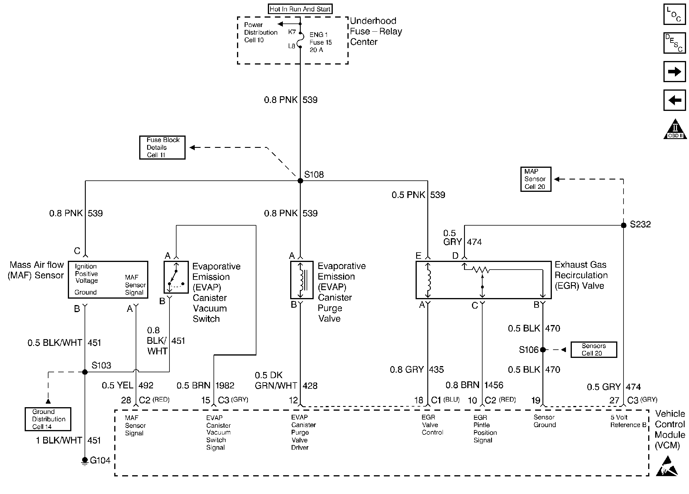
Alright, let's dive into the intricate world of the Chevy 5.7 Vortec wiring harness diagram. If you're tackling engine swaps, diagnosing electrical gremlins, or just trying to understand the guts of your classic Chevy truck or SUV, understanding this diagram is absolutely crucial. Forget fumbling around in the dark – with this guide, you'll be able to read the schematic like a pro and confidently troubleshoot electrical issues.
Why This Diagram Matters
The 5.7 Vortec engine, a staple in General Motors vehicles from the mid-90s to the early 2000s, is known for its reliability, but like any mechanical system, electrical issues can arise. A wiring harness diagram is your roadmap for diagnosing and resolving these problems. It provides a visual representation of every wire, connector, and component in the engine's electrical system. This allows you to:
- Troubleshoot Electrical Issues: Pinpoint shorts, opens, and other faults.
- Perform Engine Swaps: Integrate the 5.7 Vortec into a different vehicle.
- Upgrade or Modify: Add aftermarket components like performance chips or gauges.
- Understand the System: Gain a deeper knowledge of how your engine's electrical system functions.
- Repair Damaged Wiring: Replace damaged sections of the harness without rewiring the entire system blindly.
Key Specs and Main Parts of the 5.7 Vortec Wiring Harness
Before we decipher the diagram, let's familiarize ourselves with the major players in the 5.7 Vortec electrical system. Keep in mind that slight variations may exist depending on the specific year and vehicle model.
- Engine Control Module (ECM): The brain of the operation, responsible for managing fuel injection, ignition timing, and emissions. It receives signals from various sensors and actuators. Also often referred to as the Powertrain Control Module (PCM) if it also controls the transmission.
- Sensors:
- Mass Airflow (MAF) Sensor: Measures the amount of air entering the engine.
- Throttle Position Sensor (TPS): Monitors the throttle plate angle.
- Manifold Absolute Pressure (MAP) Sensor: Senses the pressure inside the intake manifold.
- Coolant Temperature Sensor (CTS): Measures the engine coolant temperature.
- Oxygen (O2) Sensors: Monitor the oxygen content in the exhaust gas. (Typically two sensors upstream of the catalytic converter and one downstream)
- Crankshaft Position Sensor (CKP): Determines the crankshaft position and engine speed.
- Camshaft Position Sensor (CMP): Determines the camshaft position to help with sequential fuel injection.
- Actuators:
- Fuel Injectors: Deliver fuel into the cylinders.
- Ignition Coil: Provides the high voltage spark to the spark plugs. Often one coil per cylinder in the Vortec, in a coil-near-plug configuration.
- Idle Air Control (IAC) Valve: Regulates the amount of air bypassing the throttle plate at idle.
- EGR Valve: Recirculates exhaust gases to reduce emissions.
- Connectors: Provide secure electrical connections between components. Often color-coded and keyed for easy identification.
- Relays: Electrically operated switches that control high-current circuits.
- Fuses: Protect circuits from overloads.
- Wiring Harness: A bundle of wires that connects all the components. Typically wrapped in protective tape or conduit.
Decoding the Symbols: Lines, Colors, and Icons
Understanding the symbology of the wiring harness diagram is paramount. Here's a breakdown of common symbols:
- Lines: Represent wires. The thickness of the line may indicate the wire gauge (thicker lines = thicker wires).
- Colors: Each wire is color-coded. A key will be included with the diagram, defining what each color represents (e.g., RED = Battery Voltage, BLK = Ground, WHT = White, GRN = Green, BLU = Blue). Often, wires will be striped with a second color for further identification (e.g., BLU/WHT = Blue with White Stripe).
- Connectors: Shown as circles, squares, or other geometric shapes, often with a number indicating the pin location within the connector. Connector identification numbers are crucial for pinpointing connections.
- Ground Symbols: Indicate a connection to the vehicle's chassis ground. Looks like a series of downward-pointing lines or a trident.
- Component Symbols: Each component (ECM, sensor, actuator) has its own unique symbol. A legend on the diagram will define these symbols. For example, a resistor might be represented by a jagged line.
- Splices: Points where multiple wires connect. These are often shown as dots or small circles where lines intersect.
Pay close attention to the legend or key provided with the diagram. It's the Rosetta Stone for deciphering the specific symbols and color codes used.
How It Works: Following the Electrical Flow
The diagram illustrates how electricity flows through the system. Typically, power (12V) is supplied from the battery to various components via fuses and relays. The ECM controls many actuators by switching the ground connection, completing the circuit and activating the device. Sensors send signals back to the ECM, allowing it to monitor engine conditions and make adjustments. By tracing the lines and following the color codes, you can understand how each component interacts with the others.
Example: Let's say you're troubleshooting a non-firing fuel injector. The diagram will show you the power supply wire (likely RED or ORANGE) feeding the injector, the ground wire (likely BLK or BRN) controlled by the ECM, and any intermediate connectors or splices. You can then use a multimeter to check for voltage and continuity along this circuit.
Real-World Use: Basic Troubleshooting Tips
Here's how to put your newfound diagram-reading skills to work:
- Identify the Problem Area: Use your scan tool to retrieve diagnostic trouble codes (DTCs). These codes will point you to the general area of the fault (e.g., "MAF Sensor Circuit Low").
- Locate the Relevant Circuit on the Diagram: Find the MAF sensor circuit on the wiring diagram and trace its connections to the ECM and power source.
- Check for Voltage and Continuity: Use a multimeter to verify that the sensor is receiving power and ground. Also, check for continuity in the wiring between the sensor and the ECM.
- Inspect Connectors: Look for corrosion, loose connections, or damaged wires at the connectors.
- Test Components: Use the diagram to identify the proper pins for testing the sensor or actuator's resistance or voltage output.
Example: If the diagram shows that the MAF sensor receives 12V on one pin and ground on another, use a multimeter to check for these voltages with the ignition on. If either voltage is missing, trace the wiring back to the power source or ground to find the break in the circuit.
Safety First: Highlighting Risky Components
Working with automotive electrical systems can be dangerous. Always take the following precautions:
- Disconnect the Battery: Before working on any electrical component, disconnect the negative battery cable to prevent shorts and potential electrocution.
- Work in a Well-Ventilated Area: When working with fuel-related components, ensure proper ventilation to avoid inhaling harmful vapors.
- Avoid Damaged Wires: Do not handle wires with exposed conductors. Repair or replace damaged wiring immediately.
- Use Proper Tools: Use insulated tools to prevent shorts and shocks.
- Be Aware of High-Voltage Circuits: The ignition system generates high voltage. Avoid touching ignition components while the engine is running or the ignition is on.
The ignition coil pack system can deliver a painful and potentially dangerous shock. Exercise extreme caution when working around these components.
Get Your Diagram!
We have compiled a comprehensive 5.7 Vortec wiring harness diagram specifically tailored for your needs. This valuable resource will be an indispensable tool for all your repair and modification projects. This diagram can be downloaded in PDF format. This detailed schematic will provide you with a clear and concise visual representation of the entire electrical system.
By combining this diagram with the knowledge you have gained from this article, you'll be well-equipped to tackle any electrical challenge that comes your way. Happy wrenching!