
Chevy Express Van Trailer Wiring Harness
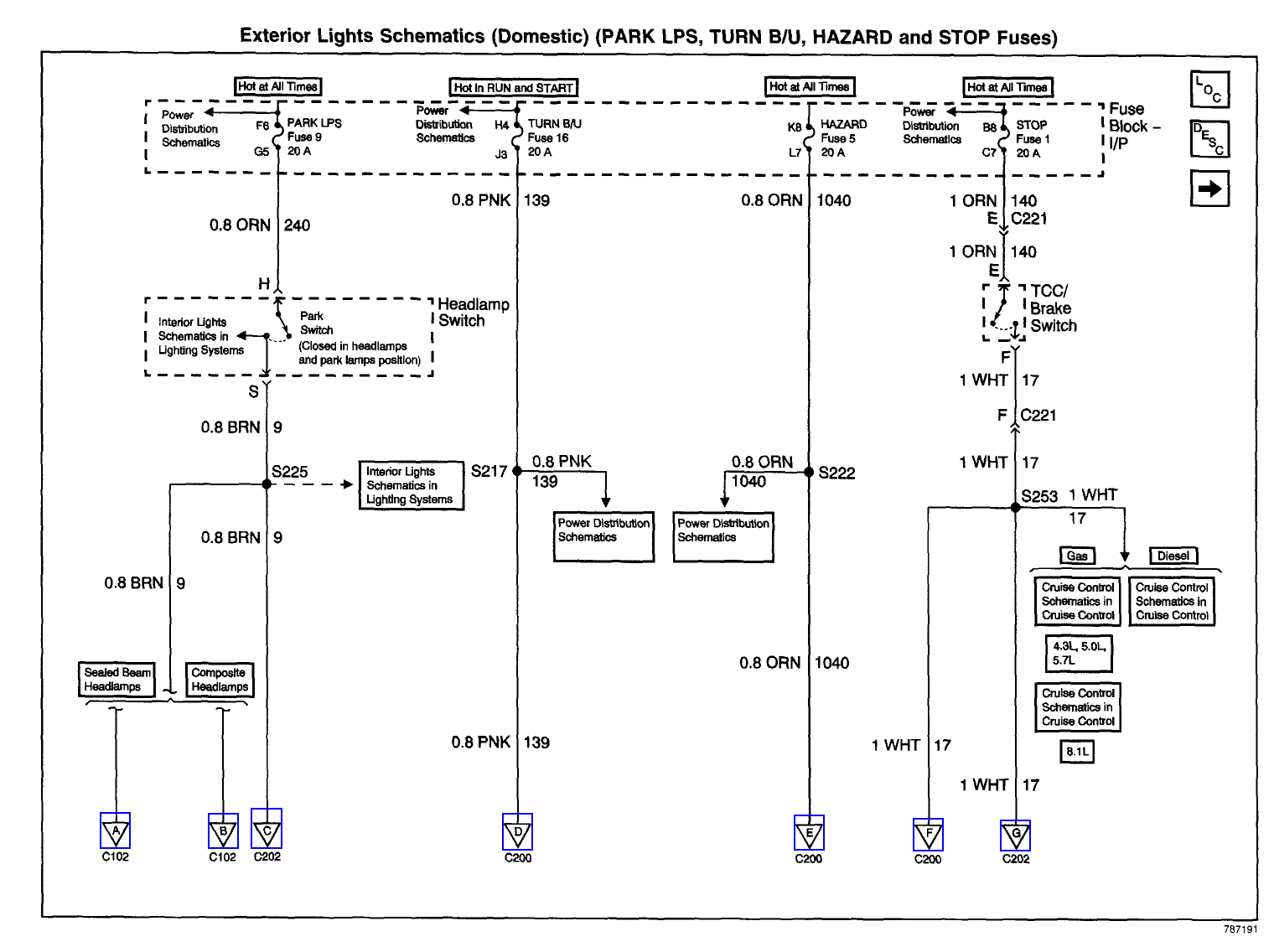
Alright, let's dive into the world of trailer wiring harnesses for your Chevy Express Van. Whether you're hauling equipment for work, gear for a weekend adventure, or a camper for a road trip, a properly installed and functioning trailer wiring harness is essential. This article will break down the intricacies of a typical Chevy Express Van trailer wiring harness diagram, giving you the knowledge you need for repairs, upgrades, or simply understanding how it all works. We'll cover the key components, the diagram symbols, troubleshooting tips, and vital safety considerations.
Why Understanding the Wiring Diagram Matters
A trailer wiring harness diagram is your roadmap when things go wrong, or when you're planning an upgrade. It's not just about connecting wires; it's about connecting them correctly and safely. Here's why understanding the diagram is crucial:
- Troubleshooting: When your trailer lights aren't working (brake lights, turn signals, running lights), the diagram is your guide to pinpointing the problem – a bad connection, a blown fuse, or a faulty wire.
- Repairs: Need to replace a damaged connector or wire? The diagram shows you exactly where each wire goes.
- Upgrades: Want to add a brake controller or a different type of trailer connector (e.g., from a 4-pin flat to a 7-pin round)? The diagram helps you integrate the new components correctly.
- Understanding: Even if you don't plan on doing any work yourself, understanding the basic layout of the wiring allows you to communicate more effectively with a mechanic and understand their explanations.
Key Specs and Main Parts of the Harness
Before we get into the diagram itself, let's identify the core components of a typical Chevy Express Van trailer wiring harness. Remember that specific configurations can vary based on the van's year, trim level, and factory towing package.
- Trailer Connector: This is the physical connection point for the trailer. Common types include:
- 4-Pin Flat: Provides basic lighting functions (ground, running lights, left turn/brake, right turn/brake). This is typically used for smaller, lighter trailers.
- 7-Pin Round: Adds features like a brake controller output (for electric trailer brakes), a 12V power supply (for charging the trailer battery), and a reverse light signal. Often found on larger trailers and RVs.
- Wiring Harness: This is the bundle of wires that connect the trailer connector to the van's electrical system. The wires are usually color-coded for easy identification.
- Converter (if needed): Some vans require a converter module. This is because the van's tail lights might use a combined signal for brake lights and turn signals (two-wire system). The converter separates these signals into dedicated brake and turn signal outputs for the trailer (three-wire system). This is more common with vans that didn't come from the factory with a tow package.
- Fuses and Relays: These protect the van's electrical system from overloads and switch higher-current circuits. The trailer wiring harness will typically have its own dedicated fuses, often located in the under-hood fuse box or a dedicated fuse box near the trailer connector.
- Ground Wire: A critical component that provides a return path for the electrical current. A poor ground connection is a common cause of trailer lighting problems.
Decoding the Symbols in the Diagram
A trailer wiring harness diagram uses a standardized set of symbols to represent different components and connections. Here's a breakdown of the most common symbols you'll encounter:
- Solid Lines: Represent wires. The thickness of the line might indicate the wire gauge (thicker lines generally mean thicker wires, capable of carrying more current).
- Dashed Lines: Often indicate a ground connection or a shielded wire.
- Color Codes: Wires are usually color-coded to aid in identification. Common colors include:
- White (WH): Typically Ground
- Brown (BN): Typically Taillights/Running Lights
- Yellow (YE): Typically Left Turn/Brake Light
- Green (GR): Typically Right Turn/Brake Light
- Blue (BU): Typically Brake Controller Output (for electric brakes)
- Red (RD): Typically 12V Power Supply
- Black (BK): Typically 12V Power Supply (can sometimes be ground)
- Circles or Squares: Represent connectors, fuses, relays, or other components. The diagram will usually include a key or legend to identify what each symbol represents.
- Ground Symbol: Looks like an inverted triangle with horizontal lines. Indicates a connection to the vehicle's chassis for grounding.
How the Trailer Wiring Harness Works
The trailer wiring harness essentially taps into the van's existing lighting circuits and provides separate outputs for the trailer lights. Here's a simplified explanation of the basic functionality:
- Power Source: The system draws power from the van's battery through fused circuits.
- Signal Input: When you activate the van's lights (headlights, turn signals, brake lights), the corresponding signals are sent to the trailer wiring harness.
- Signal Conversion (if applicable): If a converter is present, it separates the combined brake/turn signal from the van into separate outputs for the trailer.
- Output to Trailer Connector: The converted signals are then sent to the appropriate pins on the trailer connector.
- Trailer Lights: When the trailer is connected, these signals activate the corresponding lights on the trailer.
Real-World Use: Basic Troubleshooting Tips
Here are a few common problems and troubleshooting steps you can take using the wiring diagram:
- No Lights at All:
- Check the fuses associated with the trailer wiring harness. Replace any blown fuses with the correct amperage rating.
- Verify the ground connection. Ensure the ground wire is securely attached to a clean, rust-free metal surface on the van's chassis.
- Use a multimeter to check for voltage at the trailer connector pins when the corresponding lights are activated on the van. If there's no voltage, the problem is likely in the van's wiring or the converter.
- One or More Lights Not Working:
- Check the bulb on the trailer.
- Inspect the wiring and connectors on the trailer for corrosion or damage.
- Use the wiring diagram to trace the wire from the trailer connector back to the source on the van. Look for breaks, shorts, or loose connections.
- Brake Lights Not Working (with Electric Brakes):
- Check the brake controller. Ensure it's properly connected and calibrated.
- Check the blue wire (brake controller output) for voltage when the brake pedal is pressed.
- Inspect the wiring to the trailer's brake magnets.
Safety First: Highlight Risky Components
Working with electrical systems can be dangerous. Here are some critical safety precautions to keep in mind:
- Disconnect the Battery: Before working on any electrical wiring, disconnect the negative terminal of the van's battery. This prevents accidental shorts and electrical shocks.
- Use a Multimeter: A multimeter is your best friend for diagnosing electrical problems. Use it to check for voltage, continuity, and resistance.
- Proper Wire Gauge: Always use the correct wire gauge for the application. Using too small of a wire can cause overheating and fires. Refer to the wiring diagram and online resources for appropriate wire gauge selection.
- Secure Connections: Ensure all connections are secure and properly insulated. Use heat shrink tubing or electrical tape to protect exposed wires.
- Avoid Shortcuts: Don't bypass fuses or relays. They are there to protect the electrical system.
- Consider Professional Help: If you are not comfortable working with electrical wiring, consult a qualified mechanic or electrician.
We have a detailed wiring diagram available for download to help you with your project. Having the right diagram specific to your van model and year can significantly simplify the troubleshooting and repair process.