
Chevy Front Differential Parts Diagram
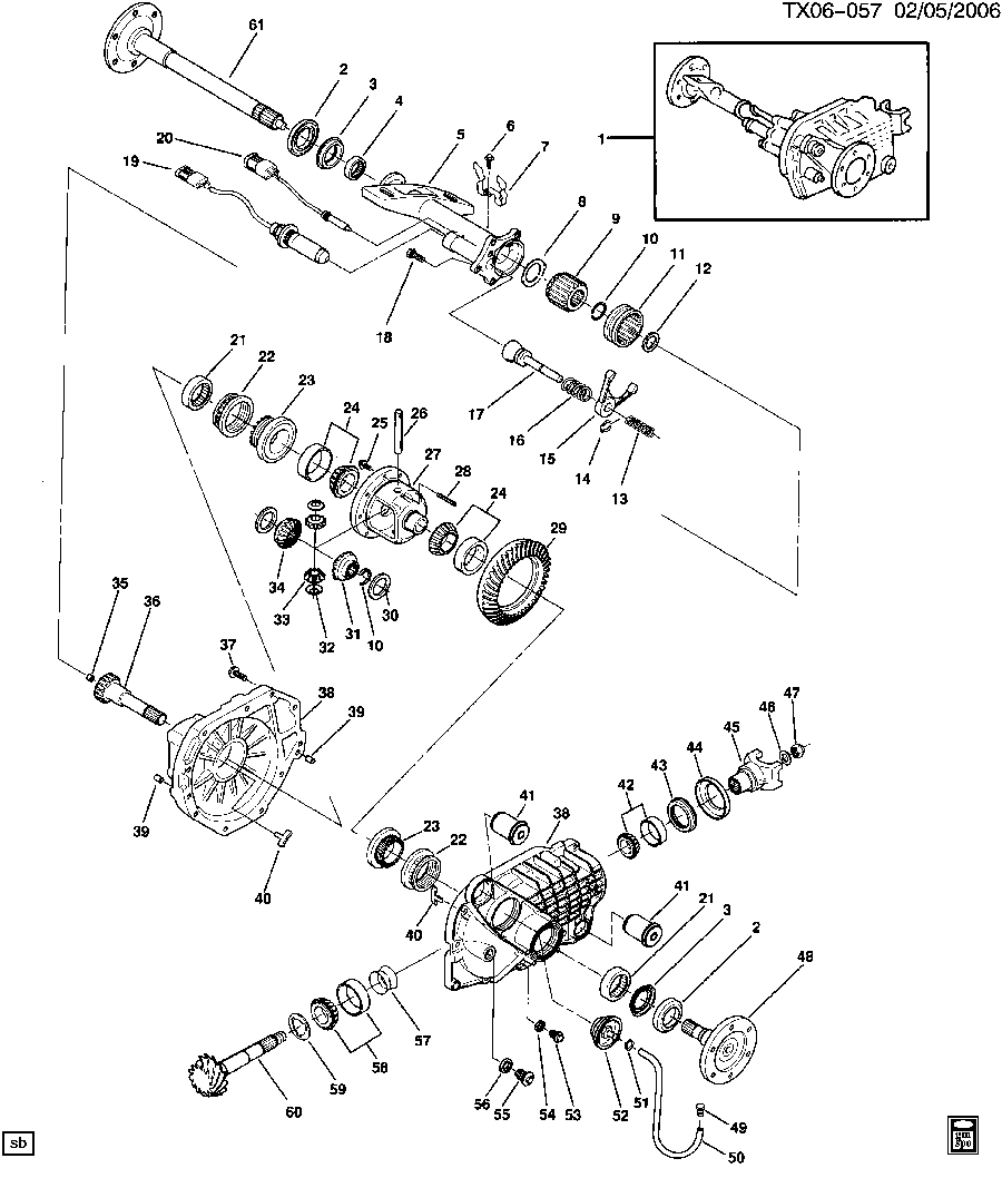
So, you’re diving into the world of Chevy front differentials, huh? That's great! Whether you're tackling a repair, planning a modification, or simply curious about what makes your 4x4 tick, understanding the front differential is crucial. A parts diagram is your roadmap through this complex assembly. This article will break down the Chevy front differential parts diagram, making it easier to understand and use for your projects.
Purpose of the Diagram
Why bother with a parts diagram? Well, think of it as the blueprint for your differential. Its primary purposes are:
- Identification: Correctly identifying each component is paramount when ordering replacement parts. No more guessing games!
- Assembly/Disassembly: The diagram shows how everything fits together. This is indispensable when taking apart a differential for repair or modification and putting it back together correctly.
- Troubleshooting: By visually seeing the relationship between parts, you can better understand how a failure in one area might affect others.
- Reference: Simply knowing the names and locations of the parts aids in general understanding and communication when discussing repairs with other mechanics or online forums.
- Parts Ordering: The diagram often includes part numbers, streamlining the parts ordering process and minimizing errors.
We have a downloadable Chevy front differential parts diagram available for you. Look for the download link at the end of this article.
Key Specs and Main Parts
Chevy front differentials vary depending on the vehicle model (e.g., Silverado, Tahoe, Colorado) and year. Therefore, it's crucial to use a diagram specific to your vehicle. However, some key components are consistent across most models:
- Differential Case (Housing): The main body that contains all the internal components. It's a robust, heavy-duty casting.
- Ring Gear: A large gear bolted to the differential carrier. It receives power from the pinion gear.
- Pinion Gear: A smaller gear that meshes with the ring gear. It receives power from the driveshaft. Gear ratio is the relationship between the pinion and ring gear. A higher ratio generally provides better low-end torque, while a lower ratio offers better fuel economy.
- Differential Carrier (Case): Holds the spider gears and side gears.
- Spider Gears (Pinion Gears): Small gears within the differential carrier that allow the wheels to turn at different speeds.
- Side Gears: Gears splined to the axle shafts.
- Axle Shafts: Transmit power from the side gears to the wheels.
- Bearings: Support the rotating components (pinion, carrier, axles) and allow for smooth operation. Common types include tapered roller bearings and ball bearings.
- Seals: Prevent oil leaks. Common types include pinion seals and axle seals.
- Yoke (Pinion Flange): Connects the driveshaft to the pinion gear.
- Shims: Used to adjust bearing preload and gear mesh.
- Locking Mechanism (if equipped): Some differentials have locking mechanisms (e.g., limited-slip, locking differentials) for improved traction in off-road conditions.
Key Specs: When looking at a diagram, pay attention to specs like:
- Gear Ratio: A crucial specification that affects vehicle performance.
- Bearing Sizes and Types: Critical for ordering the correct replacement bearings.
- Torque Specifications: Essential for proper assembly and preventing damage.
Symbols and Conventions
Parts diagrams aren't just pretty pictures; they use standardized symbols and conventions to convey information. Here's a breakdown:
- Lines:
- Solid Lines: Indicate a physical connection between parts.
- Dashed Lines: May indicate hidden parts or components located behind other parts.
- Leader Lines: Connect a part to its label or callout.
- Exploded Views: The most common type of diagram, showing parts separated from each other in their relative positions. This helps visualize the assembly process.
- Callouts: Numbers or letters referencing a parts list.
- Shading/Cross-hatching: Can be used to differentiate materials or indicate surfaces that are machined.
- Arrows: Might indicate the direction of movement or flow (e.g., oil flow).
Colors are not typically used in mechanical diagrams of this sort. The focus is on clarity of shape and connection.
How It Works
The Chevy front differential's job is to transfer power from the engine (via the driveshaft) to the front wheels while allowing them to rotate at different speeds, especially during turns.
- The driveshaft spins the pinion gear.
- The pinion gear turns the ring gear, which is bolted to the differential carrier.
- The differential carrier houses the spider gears and side gears.
- When driving straight, the spider gears do not rotate relative to the carrier, and both axle shafts turn at the same speed.
- When turning, the spider gears rotate, allowing the outer wheel to turn faster than the inner wheel. This prevents binding and tire slippage.
Limited-slip differentials and locking differentials modify this behavior to improve traction. A limited-slip differential allows some differential action but resists it when one wheel loses traction. A locking differential forces both wheels to turn at the same speed, regardless of traction, which is ideal for extreme off-road conditions.
Real-World Use: Basic Troubleshooting
The parts diagram can be invaluable when troubleshooting differential problems. Here are a few common scenarios:
- Leaking Oil: Identify the potential source of the leak (pinion seal, axle seal, housing gasket). The diagram will show you the location of these seals.
- Noise (Whining, Howling): Could indicate worn bearings, improper gear mesh, or low oil level. The diagram helps you pinpoint the location of the bearings and gears.
- Vibration: Might be caused by a bent axle shaft, damaged u-joints, or an unbalanced driveshaft. The diagram highlights these components.
- Clunking: Could indicate worn spider gears, broken axle shafts, or excessive backlash. The diagram shows the relationship between these parts.
Example: If you hear a whining noise that changes with speed, consult the diagram and focus your investigation on the pinion and ring gear, along with their bearings. Check for wear patterns, proper lubrication, and correct bearing preload.
By using the diagram, you can isolate the problem area before even taking the differential apart, saving time and effort.
Safety
Working on a differential can be dangerous. Here are some crucial safety precautions:
- Use Jack Stands: Never work under a vehicle supported only by a jack.
- Wear Safety Glasses: Protect your eyes from flying debris and chemicals.
- Use Gloves: Protect your hands from sharp edges and chemicals.
- Proper Tools: Use the correct tools for the job. Improper tools can damage components and cause injury.
- Torque Wrench: Always use a torque wrench to tighten fasteners to the specified torque.
- Heavy Components: The differential case and axle shafts are heavy. Use proper lifting techniques or a mechanical lift.
- Crush Sleeve: The pinion gear often utilizes a crush sleeve. Be aware that excessive force to compress the crush sleeve will ruin it.
- Chemicals: Gear oil can be harmful. Wear gloves and avoid contact with skin and eyes.
Important! Be extremely careful when dealing with preloaded components like the pinion gear. Improper disassembly or assembly can lead to serious injury.
Armed with this information and our downloadable Chevy front differential parts diagram, you're well on your way to understanding and working on your vehicle's differential with confidence. Remember to always consult your vehicle's service manual for specific procedures and torque specifications.
Download the Chevy Front Differential Parts Diagram: [Download Here - Placeholder] (Replace this with your actual download link)