Chevy Ignition Switch Wiring Diagram
Understanding your Chevy's ignition switch wiring diagram is crucial for a range of tasks, from basic troubleshooting to more complex modifications and repairs. Whether you're dealing with a no-start condition, installing a remote starter, or simply expanding your automotive knowledge, this guide will provide you with a clear and concise breakdown of the ignition switch wiring system in your Chevy.
Why You Need This Diagram
The ignition switch is a critical component in your vehicle's starting and electrical system. It's the gatekeeper, controlling the flow of power to various circuits depending on the key position. A faulty ignition switch or damaged wiring can lead to frustrating problems, including:
- No-start conditions: The engine won't crank or turn over.
- Engine stalls: The engine unexpectedly shuts off while driving.
- Accessory issues: Radio, wipers, or other accessories not working properly.
- Battery drain: Parasitic drain due to a faulty switch.
Having access to the wiring diagram allows you to:
- Diagnose problems: Pinpoint the source of electrical issues.
- Perform repairs: Replace faulty wiring or the ignition switch itself.
- Install aftermarket accessories: Connect remote starters, alarms, or other devices safely.
- Gain a deeper understanding: Learn how your car's electrical system works.
Key Specs and Main Parts
Before diving into the diagram, it's important to understand the main components involved and their basic specifications. Keep in mind that the specific wiring and component names may vary slightly depending on your Chevy model and year. Refer to the specific diagram for your vehicle.
Essential Components:
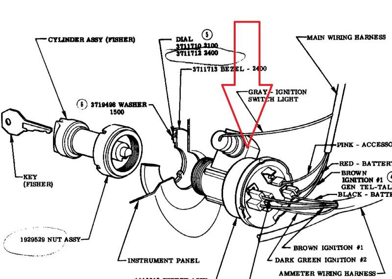
- Ignition Switch: The central component, typically located on the steering column. It has multiple positions (Off, Accessory, Run, Start) that control the flow of power to different circuits.
- Battery: The power source for the entire electrical system. Typically a 12V system.
- Starter Solenoid: An electromagnetic switch that engages the starter motor. The ignition switch's "Start" position triggers the solenoid.
- Fuse Box/Distribution Block: A central location for fuses and relays that protect and distribute power to various circuits.
- Relays: Electrically operated switches that allow a low-current circuit (from the ignition switch) to control a high-current circuit (like the starter motor).
- Wiring Harness: A bundle of wires that connect the various components of the electrical system.
Typical Wire Gauges:
The gauge of the wire (its thickness) is important for carrying the correct amount of current. Common gauges found in ignition switch circuits include:
- 10-12 Gauge: Used for high-current circuits like the starter motor.
- 14-16 Gauge: Used for accessory circuits and general power distribution.
- 18-20 Gauge: Used for low-current control circuits.
Decoding the Symbols: Lines, Colors, and Icons
Understanding the symbols used in the wiring diagram is crucial for accurate interpretation. Here's a breakdown of common symbols:
Lines:
- Solid Line: Represents a wire or conductor.
- Dashed Line: May represent a shielded wire, a wire within a harness, or a ground connection.
- Line with a Slash: Indicates a wire splice or connection point.
- Line Crossing Another Line (Without a Dot): Indicates that the wires are crossing but not connected.
- Line Crossing Another Line (With a Dot): Indicates that the wires are connected at that point.
Colors:
Wire colors are standardized to help identify circuits. Some common colors include:
- Red: Typically indicates a power wire coming directly from the battery.
- Black: Typically indicates a ground wire.
- Yellow: Often used for accessory circuits.
- Blue: May be used for ignition or control circuits.
- Orange: Can indicate a power wire that is hot at all times, even with the ignition off.
- Green: Often used for lighting circuits.
The diagram will usually have a color code key to specify what each color represents.
Icons:
- Rectangle: Can represent a relay, switch, or other electrical component.
- Circle: May represent a light bulb, sensor, or other round component.
- Fuse Symbol: A zigzag line enclosed in a rectangle, indicating a fuse.
- Ground Symbol: A series of descending lines, indicating a connection to the vehicle's chassis (ground).
- Battery Symbol: A series of alternating long and short lines, representing the battery's positive and negative terminals.
How It Works: A Simplified Explanation
The ignition switch acts as a multi-pole, multi-throw switch. Here's a simplified explanation of what happens in each key position:
- Off: No circuits are energized (except potentially some always-hot circuits for things like the clock or alarm system).
- Accessory: Power is supplied to accessories like the radio, wipers, and cigarette lighter. The engine is not running.
- Run: Power is supplied to the engine control unit (ECU), fuel pump, ignition system, and other essential components required for the engine to run.
- Start: The ignition switch sends a signal to the starter solenoid, which engages the starter motor to crank the engine. Once the engine starts, the key is released back to the "Run" position.
The diagram will show which wires are connected in each position, allowing you to trace the flow of electricity.
Real-World Use: Basic Troubleshooting Tips
Here are some basic troubleshooting tips using the wiring diagram:
- No Crank, No Start: Use a multimeter to check for voltage at the starter solenoid when the key is in the "Start" position. If there's no voltage, trace the wiring back to the ignition switch and check for continuity (using the multimeter) to identify breaks in the wire. Also, check the starter relay and its corresponding fuse.
- Accessory Issues: If the accessories aren't working in the "Accessory" position, use the diagram to identify the wire that powers the accessory circuit. Check for voltage at the accessory fuse and then at the accessory itself.
- Battery Drain: A parasitic draw can sometimes be traced back to a faulty ignition switch that isn't completely shutting off certain circuits. Disconnect the battery negative terminal and use a multimeter in amp mode to measure the current draw. Then, systematically disconnect circuits (starting with those controlled by the ignition switch) to identify the circuit causing the draw.
Remember to always disconnect the battery negative terminal before working on any electrical components.
Safety Considerations
Working with automotive electrical systems can be dangerous. Here are some important safety precautions:
- Disconnect the Battery: Always disconnect the battery negative terminal before working on any electrical components. This prevents accidental shorts and potential electrical shocks.
- Wear Safety Glasses: Protect your eyes from sparks and debris.
- Use Insulated Tools: Use tools with insulated handles to prevent electrical shock.
- Avoid Water: Never work on electrical systems in wet conditions.
- High-Current Circuits: Be extremely careful when working with high-current circuits like the starter motor. Shorting these circuits can cause serious damage and injury. The wires that supply the starter are risky and require respect.
- Consult a Professional: If you're not comfortable working on electrical systems, consult a qualified mechanic.
Understanding and correctly using the Chevy Ignition Switch Wiring Diagram will empower you to diagnose, repair, and modify your vehicle's electrical system safely and effectively. Now you're equipped to put your newfound knowledge into action!