
Chevy Silverado Fuel Pump Wiring Diagram
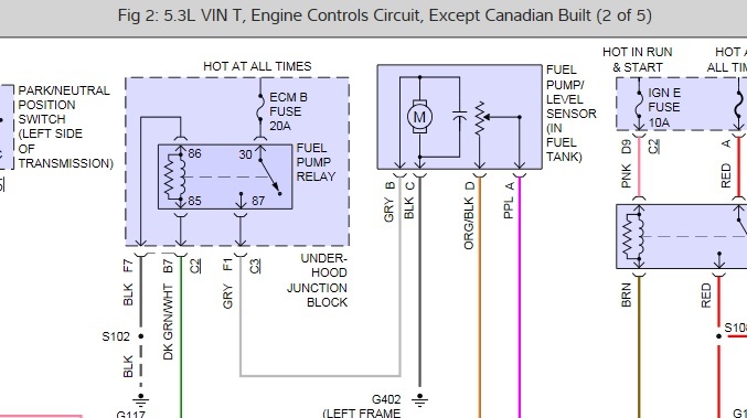
Understanding the fuel pump wiring diagram for your Chevy Silverado is crucial for a variety of tasks, from simple repairs to performance modifications. This article serves as a comprehensive guide to help experienced DIYers navigate the intricacies of this vital system. Whether you're diagnosing a no-start condition, upgrading your fuel pump for more power, or simply learning more about your truck, this knowledge will prove invaluable.
Purpose of Understanding the Fuel Pump Wiring Diagram
The fuel pump wiring diagram is your roadmap to the electrical circuitry controlling the fuel pump. It's essential for:
- Troubleshooting Fuel Pump Issues: Pinpointing the exact cause of a fuel pump failure, whether it's a blown fuse, a faulty relay, a broken wire, or a failing pump itself.
- Performing Fuel Pump Replacements: Ensuring proper wiring connections when installing a new fuel pump.
- Upgrading Fuel Systems: Modifying the fuel system to accommodate higher-flowing pumps for performance enhancements.
- Installing Aftermarket Accessories: Integrating fuel pressure regulators, fuel pump controllers, or other aftermarket fuel system components.
- Understanding Vehicle Electrics: Gaining a deeper understanding of how the electrical system interacts with the fuel delivery system.
Key Specs and Main Parts
Before diving into the diagram itself, let's identify the key components and specifications commonly found in a Chevy Silverado fuel pump circuit:
- Fuel Pump: The electric pump itself, typically located inside the fuel tank. It draws fuel from the tank and delivers it to the fuel injectors. The voltage typically ranges from 12V to 14V when operating.
- Fuel Pump Relay: An electrically operated switch that controls the power supply to the fuel pump. This relay is triggered by the Powertrain Control Module (PCM).
- Fuel Pump Fuse: A safety device that protects the fuel pump circuit from overcurrent. Amperage ratings vary by model year and engine, but are typically between 15A and 20A.
- Inertia Switch (Fuel Cutoff Switch): In some models, a safety device that cuts power to the fuel pump in the event of a collision.
- Powertrain Control Module (PCM): The "brain" of the engine management system. It controls the fuel pump relay based on various sensor inputs.
- Fuel Pump Driver Module (FPDM): Some newer models utilize an FPDM, which allows the PCM to control the fuel pump speed and pressure more precisely. This enables variable fuel delivery based on engine demand, improving efficiency.
- Wiring Harness: The network of wires that connects all the components in the fuel pump circuit. Wire gauge (thickness) is crucial for handling the current draw of the fuel pump.
- Ground Connection: A solid connection to the vehicle chassis is essential for completing the fuel pump circuit.
Understanding Diagram Symbols
A fuel pump wiring diagram uses standardized symbols to represent electrical components and connections. Here’s a breakdown of the common symbols you'll encounter:
- Lines: Represent wires. Solid lines indicate a direct connection, while dashed lines may indicate a shielded wire or a less critical connection. Wire thickness can sometimes be indicated to represent wire gauge.
- Colors: Wires are color-coded for easy identification. Common colors include red (power), black (ground), and various other colors for signal wires. The diagram legend will always define what each color represents.
- Relay Symbol: A coil symbol represents the relay coil, and a switch symbol represents the relay contacts (normally open or normally closed).
- Fuse Symbol: A squiggly line inside a rectangle represents a fuse.
- Ground Symbol: A series of descending horizontal lines represents a ground connection.
- Connector Symbol: A circle or square with lines entering or exiting represents a connector.
- PCM Symbol: Often represented by a rectangle with labels indicating input and output pins.
Important Wire Color Note: Always verify the wire colors on *your* specific vehicle, as variations can occur even within the same model year.
How It Works: Following the Circuit
Here's a simplified explanation of how the fuel pump circuit typically operates:
- When the ignition key is turned to the "ON" position, the PCM sends a brief signal to the fuel pump relay. This primes the fuel system by running the pump for a few seconds.
- Once the engine starts and the PCM receives signals from the crankshaft position sensor and other sensors, it continues to activate the fuel pump relay.
- The activated relay allows battery voltage to flow through the fuel pump fuse and then to the fuel pump.
- The fuel pump draws fuel from the tank and sends it to the fuel injectors.
- In systems with an FPDM, the PCM sends signals to the FPDM, which then controls the voltage supplied to the fuel pump, adjusting the fuel delivery rate based on engine demand.
- The fuel pump is grounded to the vehicle chassis, completing the circuit.
If any of these steps fail (e.g., blown fuse, faulty relay, broken wire), the fuel pump will not operate, and the engine will not start or will stall.
Real-World Use: Basic Troubleshooting Tips
Here's how you can use the fuel pump wiring diagram to troubleshoot common problems:
- No Fuel Pump Noise:
- Check the fuel pump fuse for continuity using a multimeter. If the fuse is blown, replace it. If it blows again, there's a short circuit in the system.
- Locate the fuel pump relay and test it. You can swap it with a known good relay (e.g., the horn relay, which is often the same type) to see if that resolves the issue.
- Use a multimeter to check for voltage at the fuel pump connector when the ignition is turned on. If there's no voltage, trace the wiring back to the relay and fuse, looking for breaks or shorts.
- Check the ground connection for corrosion or looseness. Clean and tighten the ground connection.
- Engine Stalling:
- Check fuel pressure at the fuel rail using a fuel pressure gauge. Low fuel pressure can indicate a failing fuel pump or a clogged fuel filter.
- Inspect the fuel pump wiring for loose connections or damaged insulation.
- If equipped, check the FPDM for proper operation. Faulty FPDMs can cause intermittent fuel pump problems.
Important Note: Always use a multimeter to test circuits safely. Avoid using test lights, as they can sometimes damage sensitive electronic components.
Safety: Handling Electrical Components and Fuel
Working with electrical components and fuel can be dangerous. Here are some important safety precautions:
- Disconnect the Battery: Before working on any electrical components, disconnect the negative battery cable to prevent accidental shorts or shocks.
- Work in a Well-Ventilated Area: Fuel vapors are flammable and can be harmful to breathe. Work in a well-ventilated area and avoid sparks or open flames.
- Use Appropriate Tools: Use insulated tools to prevent electrical shocks.
- Wear Safety Glasses: Protect your eyes from fuel splashes and debris.
- Handle Fuel Responsibly: Dispose of fuel properly and avoid spilling it.
- Be Mindful of Hot Components: The exhaust system and other engine components can be very hot. Allow them to cool down before working near them.
- The fuel pump itself is located *inside* the fuel tank, and working in/around a fuel tank is extremely dangerous. Even with precautions, fuel vapor can ignite. It's often best to have a professional handle fuel pump replacement if you are not experienced.
Accessing the Diagram
Understanding the fuel pump wiring diagram is the first step towards effectively diagnosing and resolving issues with your Chevy Silverado's fuel system. We have a comprehensive fuel pump wiring diagram file available for download, tailored to various Silverado model years and engine configurations. This detailed diagram will provide you with the specific information you need to tackle your fuel system projects with confidence.