
Chevy Silverado Master Cylinder Diagram
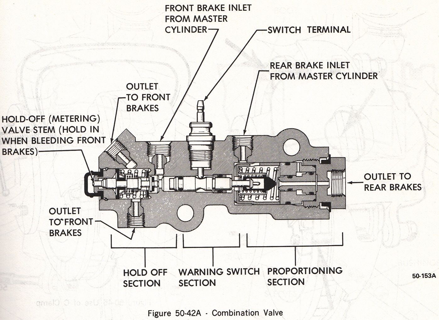
The master cylinder is the heart of your Chevy Silverado's braking system. Understanding its inner workings is crucial for effective repairs, performance upgrades, and even just general automotive knowledge. This article provides a detailed breakdown of the Chevy Silverado master cylinder diagram, equipping you with the knowledge to confidently tackle brake-related tasks. Having access to and understanding this diagram is invaluable for anyone from the experienced DIYer to the seasoned mechanic.
Purpose of the Master Cylinder Diagram
A master cylinder diagram serves multiple critical purposes:
- Troubleshooting: When experiencing brake problems like a soft pedal, leaks, or uneven braking, the diagram helps you pinpoint the source of the issue within the master cylinder itself.
- Repair & Rebuild: Whether you're replacing worn seals, overhauling the entire unit, or simply cleaning internal components, the diagram provides a visual guide to the correct assembly and placement of each part.
- Performance Upgrades: If you're upgrading your Silverado's braking system with larger calipers, rotors, or a different brake booster, understanding the master cylinder's flow rates and piston sizes is essential for proper system matching. The diagram can help determine compatibility or the need for a master cylinder upgrade.
- Educational Value: For anyone interested in automotive mechanics, studying the master cylinder diagram provides a fundamental understanding of hydraulic brake systems and their operation.
Key Specs and Main Parts
Before diving into the diagram itself, let's review the key components of a typical Chevy Silverado master cylinder (specific models and years may vary slightly, but the fundamental principles remain the same):
- Master Cylinder Body: This is the main housing, typically made of cast iron or aluminum. It contains the reservoirs and bores for the pistons.
- Reservoirs: These hold the brake fluid. Most Silverado master cylinders have two separate reservoirs – one for the front brakes and one for the rear. This split system ensures that if one circuit fails, the other will still function (though with reduced braking power).
- Primary and Secondary Pistons: These are the heart of the master cylinder. When you press the brake pedal, the pushrod actuates the primary piston, which in turn pushes the secondary piston. These pistons pressurize the brake fluid.
- Seals (Cups): These are rubber or synthetic components that seal the pistons within the bores, preventing brake fluid from leaking past. Worn or damaged seals are a common cause of master cylinder failure.
- Springs: Springs return the pistons to their resting position when the brake pedal is released.
- Residual Pressure Valves (RPVs): Some older models may have these; they maintain a slight pressure in the brake lines to help keep the wheel cylinder cups expanded, reducing pedal travel. Newer systems rely on other design features to achieve the same goal.
- Ports (Outlets): These are the connections where the brake lines attach to the master cylinder, leading to the brake calipers or wheel cylinders.
- Brake Fluid Level Sensor: This sensor monitors the brake fluid level in the reservoir and illuminates a warning light on the dashboard if the level is low.
Typical Silverado Master Cylinder Specs (Example):
- Bore Size: Commonly ranges from 1 inch to 1 1/8 inches, depending on the model year and braking system configuration. Larger bore sizes generally provide more braking force but require more pedal effort.
- Outlet Ports: Usually two, one for the front brakes and one for the rear. Port sizes are standardized (e.g., 3/8-24 inverted flare).
- Fluid Type: Most Silverados use DOT 3 or DOT 4 brake fluid. Always use the recommended fluid type specified in your owner's manual. Mixing different fluid types can damage the braking system.
Understanding Master Cylinder Diagram Symbols
Master cylinder diagrams, like all technical diagrams, use symbols to represent different components and connections. Here's a breakdown of common symbols:
- Solid Lines: Typically represent hydraulic lines carrying brake fluid under pressure. Thicker lines may indicate higher pressure lines.
- Dashed Lines: Often used for vacuum lines (related to the brake booster, if equipped) or electrical wiring associated with the brake fluid level sensor.
- Circles: Can represent pistons, seals, or small valves. The context within the diagram usually clarifies the specific component.
- Squares/Rectangles: May represent the master cylinder body or reservoir.
- Arrows: Indicate the direction of fluid flow or mechanical force.
- Numbers/Letters: These are used to identify specific components or connections, and they are usually cross-referenced to a parts list or legend accompanying the diagram.
- Color Coding: While not always present, some diagrams use color coding to differentiate between different circuits or fluid types. For example, one color might represent the front brake circuit and another the rear.
Pay close attention to the legend or key that accompanies the diagram. This is where you'll find a detailed explanation of all the symbols and abbreviations used.
How the Master Cylinder Works
The master cylinder's operation is relatively straightforward, but understanding the principle is key to troubleshooting. Here's the basic sequence of events:
- Brake Pedal Activation: When you press the brake pedal, it pushes a pushrod connected to the primary piston in the master cylinder.
- Piston Movement: The primary piston moves forward, compressing the brake fluid in front of it. This pressure then acts on the secondary piston, which is located further down the bore.
- Pressure Generation: Both pistons work together to generate hydraulic pressure within the brake lines. This pressure is transmitted equally to all the brake calipers or wheel cylinders at the wheels.
- Brake Activation: The pressure forces the pistons in the calipers or wheel cylinders to extend, pressing the brake pads against the rotors (disc brakes) or the brake shoes against the drums (drum brakes). This friction slows down or stops the vehicle.
- Release: When you release the brake pedal, the springs inside the master cylinder return the pistons to their resting positions. The pressure in the brake lines is relieved, allowing the calipers/wheel cylinders to retract, releasing the brakes.
The dual-circuit design of most modern master cylinders is a crucial safety feature. If one circuit fails (e.g., due to a leak), the other circuit will still function, providing at least partial braking power.
Real-World Use: Basic Troubleshooting
Here are some common brake problems and how a master cylinder diagram can help you diagnose them:
- Soft or Spongy Brake Pedal: This could be caused by air in the brake lines, but it can also be a sign of a failing master cylinder. Check the diagram to see if there's a leak around the piston seals. Internal leaks within the master cylinder allow fluid to bypass the pistons, resulting in a soft pedal.
- Brake Fluid Leaks: Examine the master cylinder body, reservoir connections, and outlet ports for any signs of leaks. The diagram will show you the location of seals and O-rings that are prone to leaking.
- Brake Pedal Goes to the Floor: This is a serious problem that usually indicates a major leak in the brake system. The master cylinder itself could be the culprit if the internal seals have failed completely.
- Brakes Locking Up: While less common, a faulty master cylinder can sometimes cause the brakes to lock up. This is usually due to a problem with the pressure release mechanism or a blocked return port.
Basic Troubleshooting Steps:
- Visual Inspection: Carefully inspect the master cylinder for leaks, damage, or corrosion.
- Fluid Level Check: Make sure the brake fluid reservoir is full. Low fluid levels can indicate a leak somewhere in the system.
- Brake Pedal Feel: Pay attention to the feel of the brake pedal. Is it soft, spongy, or does it sink to the floor?
- Bleeding the Brakes: If you suspect air in the lines, bleed the brakes to remove it.
Safety Considerations
Working with brake systems involves handling brake fluid, which is corrosive and can damage painted surfaces. Wear gloves and eye protection when handling brake fluid. Never reuse brake fluid that has been drained from the system.
The brake booster (if equipped) uses vacuum assistance to amplify your braking force. Be extremely careful when working on the brake booster or its vacuum lines. Improperly disconnecting or damaging the vacuum lines can result in reduced braking power and a potentially dangerous situation.
Always properly bleed the brake system after working on the master cylinder or any other part of the hydraulic brake system. Failure to do so can result in a soft pedal and reduced braking performance.
Disclaimer: This information is for general guidance only. Consult your vehicle's service manual or a qualified mechanic for specific repair procedures and safety precautions.
We have a detailed Chevy Silverado master cylinder diagram file available for download. This diagram provides a comprehensive visual aid for your repair and maintenance endeavors. Understanding this diagram will significantly enhance your ability to diagnose and address brake system issues effectively.