
Chevy Starter Solenoid Wiring Diagram
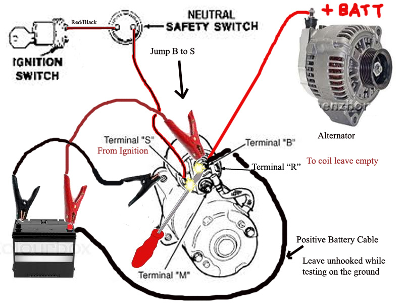
Understanding the wiring of your Chevy's starter solenoid is crucial for various reasons, from diagnosing starting problems to performing modifications or even complete engine swaps. A solid grasp of this system allows you to troubleshoot issues effectively, saving you time and money on potentially unnecessary repairs. This article will break down the Chevy starter solenoid wiring diagram, explaining its components, functionality, and practical applications. We'll provide you with the knowledge to confidently tackle starting system issues on your Chevy.
Why This Diagram Matters
The starter system is the heart of getting your engine going. When it fails, you're going nowhere. Knowing how the starter solenoid wiring diagram works is vital for:
- Troubleshooting starting problems: Is the engine cranking slowly or not at all? The wiring diagram helps pinpoint the faulty component (solenoid, starter motor, wiring, etc.).
- Performing repairs: Replacing a faulty solenoid or starter motor requires understanding how the wiring connects to ensure proper function.
- Modifications and upgrades: Upgrading your engine or electrical system might necessitate modifications to the starter wiring. A diagram is essential for safe and correct wiring.
- Engine swaps: When swapping engines, you need to integrate the starter system with the new engine's electrical system. The wiring diagram for both engines becomes invaluable.
- General understanding of automotive electrical systems: The starter circuit is a relatively simple but fundamental part of any car's electrical system. Understanding it provides a foundation for understanding more complex systems.
Key Specs and Main Parts
Let's define the key components you'll find in a typical Chevy starter solenoid wiring diagram:
- Battery: The source of electrical power for the entire vehicle. Usually a 12V DC system.
- Ignition Switch: When turned to the "start" position, it sends a signal to the starter solenoid.
- Starter Solenoid: An electromagnetic switch that engages the starter motor and provides it with high current from the battery. It typically has two main functions:
- To close a high-current circuit from the battery to the starter motor.
- To engage the starter motor's pinion gear with the engine's flywheel ring gear.
- Starter Motor: An electric motor that turns the engine's crankshaft to initiate combustion.
- Ground Connection: Provides a return path for the electrical current to the battery. Clean and secure ground connections are critical for reliable starting.
- Fuses/Fusible Links: Protective devices that prevent damage from overcurrent situations.
- Wiring Harness: A bundle of wires that connect the different components of the starter system. Wire gauge (thickness) is important for handling the high current demands of the starter motor.
Symbols and Conventions in the Wiring Diagram
Wiring diagrams use specific symbols to represent components and connections. Here's a breakdown of common symbols:
- Solid Lines: Represent wires connecting components.
- Dashed Lines: Can represent wires that are not directly part of the starter circuit, but are related or have a control function, or they could be optional wires.
- Circles or Rectangles: Represent components like the battery, ignition switch, solenoid, and starter motor. The actual shape can vary between diagrams.
- Ground Symbol (usually three horizontal lines getting shorter): Indicates a connection to the vehicle's chassis, which serves as the ground path.
- Fuse Symbol (often a squiggly line inside a rectangle): Represents a fuse.
- Relay Symbol: Represents a relay, often including a coil and a switch contact.
- Color Codes: Wires are often color-coded (e.g., red for battery power, black for ground, yellow for ignition switch signal). The wiring diagram will have a key that identifies the colors. Common abbreviations include: BK (Black), RD (Red), WH (White), BL (Blue), GN (Green), YL (Yellow), OR (Orange), BR (Brown).
- Numbers and Letters: Terminals on components are often labeled with numbers or letters (e.g., "S" terminal on the solenoid for the start signal).
How It Works
Here's a step-by-step explanation of how the Chevy starter system works:
- Turning the Key: When you turn the ignition switch to the "start" position, it sends a low-current signal (typically +12V) to the "S" terminal (start terminal) on the starter solenoid.
- Solenoid Activation: The signal energizes the solenoid's internal electromagnet.
- Pinion Gear Engagement: The energized solenoid pulls in a plunger that performs two actions: it pushes the starter motor's pinion gear into engagement with the engine's flywheel ring gear, and it closes a heavy-duty electrical contact.
- High Current to Starter Motor: Closing the electrical contact completes a high-current circuit directly from the battery to the starter motor. This high current powers the starter motor, causing it to spin rapidly.
- Engine Cranking: The spinning starter motor turns the engine's crankshaft, initiating the combustion process.
- Releasing the Key: When you release the key, the ignition switch signal to the solenoid is cut off.
- Solenoid Deactivation: The solenoid de-energizes, retracting the plunger.
- Pinion Gear Disengagement: The pinion gear disengages from the flywheel, and the electrical contact opens, stopping the starter motor.
Real-World Use: Basic Troubleshooting Tips
Here are some common starting problems and how the wiring diagram can help diagnose them:
- No Cranking, No Clicking:
- Check the battery voltage.
- Inspect the main battery cables for corrosion or looseness.
- Check the ignition switch. Use a multimeter to see if voltage reaches the "S" terminal on the solenoid when the key is in the "start" position. If not, the ignition switch or wiring between the switch and solenoid might be faulty.
- Check the ground connection. Ensure the engine and chassis have a solid ground connection to the battery.
- No Cranking, Clicking Sound:
- This often indicates a weak battery or a problem with the solenoid.
- Check the battery voltage under load (while trying to start). A significant voltage drop indicates a weak battery.
- If the battery is good, the solenoid itself might be faulty. Try bypassing the solenoid by using a jumper cable to connect the battery positive terminal directly to the starter motor positive terminal. (Caution: This bypasses safety features. Ensure the car is in park/neutral and the parking brake is engaged!) If the starter motor engages, the solenoid is likely the problem.
- Slow Cranking:
- Check the battery voltage and charging system.
- Inspect the starter motor and solenoid for excessive corrosion or damage.
- Poor ground connections can also cause slow cranking.
Safety Considerations
Working on the starter system involves high-current circuits, so safety is paramount:
- Disconnect the Battery: Always disconnect the negative battery cable before working on the electrical system. This prevents accidental shorts and electrical shocks.
- High Current: The starter system uses extremely high current. Avoid touching any exposed terminals or wires while the system is energized.
- Bypassing the Solenoid: Bypassing the solenoid is a useful diagnostic technique, but it also bypasses safety interlocks (like the neutral safety switch). Ensure the car is in park/neutral and the parking brake is firmly engaged before attempting this.
- Fuel Lines: Be careful not to damage any fuel lines while working near the starter. A fuel leak near electrical sparks can create a serious fire hazard.
- Eye Protection: Wear safety glasses to protect your eyes from flying debris or sparks.
Remember, electrical systems can be complex. If you're not comfortable working on the starter system, it's always best to consult a qualified mechanic.
To further assist you, we have a sample Chevy Starter Solenoid Wiring Diagram file available for download. This diagram will provide a visual aid to complement the information provided in this article.