Chevy Steering Column Wiring Diagram
So, you're diving into the wonderful world of Chevy steering column wiring, eh? Whether you're chasing down a gremlin in your turn signals, retrofitting a classic, or adding some aftermarket goodies, understanding your steering column wiring diagram is absolutely crucial. Forget blindly poking around with a test light – this is your roadmap. This article will break down everything you need to know, from deciphering those cryptic symbols to basic troubleshooting, so you can tackle your project with confidence.
Purpose of the Steering Column Wiring Diagram
Why bother with a diagram in the first place? Several reasons. Foremost, it's indispensable for accurate repairs. Diagnosing electrical problems in the steering column – faulty turn signals, horn issues, ignition problems – becomes infinitely easier with a clear wiring schematic. Secondly, it's invaluable for modifications. Planning to install a new steering wheel with integrated controls? You'll need to know which wires do what. And finally, it provides a deeper understanding of your vehicle's electrical system. Seeing how everything connects demystifies the system and empowers you to handle future issues.
Key Specs and Main Parts
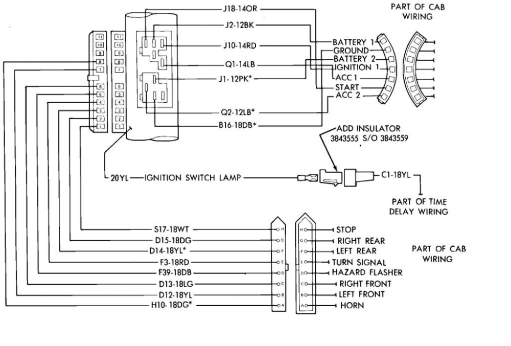
Let's talk about what you'll typically find in a Chevy steering column wiring diagram. It's not just a bunch of lines and symbols; it's a detailed representation of the circuit. Here are the main components you'll encounter:
- Ignition Switch: This is the heart of the electrical system. It controls power distribution to various circuits based on the key position (Off, Acc, Run, Start). Expect to see multiple wires leading in and out, each corresponding to a specific function.
- Turn Signal Switch: A complex switch with numerous wires controlling the front and rear turn signals, hazard lights, and sometimes even cruise control deactivation.
- Dimmer Switch: Located within the turn signal switch assembly (typically), it controls the high and low beams.
- Horn Contact: Often a simple button or contact that grounds the horn relay circuit.
- Tilt Mechanism: If equipped, this may have wires related to a memory feature or adjustable pedals if those functions are integrated into the steering column.
- Airbag Connector (SRS): A critical component that requires extreme caution. We'll cover safety aspects later. This connects the airbag module to the vehicle's wiring harness.
- Cruise Control Switches: If equipped, these will have wires related to setting, resuming, canceling, and adjusting cruise speed.
- Multi-Function Switch: Many modern vehicles combine multiple functions into a single switch, further complicating the wiring (windshield wipers, etc.).
- Wiring Harness and Connectors: The bundle of wires that connect all these components. Pay attention to connector types and pin arrangements.
Key Specs to look for in the diagram itself:
- Wire Gauge (AWG): The thickness of the wire. Thicker wires can handle more current. The diagram will specify the gauge for each wire.
- Wire Color Codes: Each wire has a specific color (or color combination) to identify its function. The diagram will include a color code chart.
- Circuit Numbers: Each circuit will often be assigned a number, which can be helpful when tracing wires.
- Fuse/Relay Locations: The diagram may indicate which fuse or relay protects a particular circuit connected to the steering column.
Decoding the Symbols: Lines, Colors, and Icons
Wiring diagrams use a standardized set of symbols to represent electrical components and connections. Learning these symbols is key to understanding the diagram. Here's a breakdown:
- Lines: Represent wires. Solid lines are typically current-carrying wires, while dashed lines may indicate grounds or shielded wires.
- Colors: Each wire is assigned a specific color, identified by abbreviations (e.g., BLK for black, RED for red, GRN for green, WHT for white, BLU for blue, YEL for yellow, ORN for orange, BRN for brown, GRY for gray). Some wires may have a primary color and a stripe color (e.g., GRN/WHT indicates a green wire with a white stripe).
- Ground Symbols: Usually represented by a series of horizontal lines, indicating a connection to the vehicle's chassis ground.
- Connector Symbols: Show where wires connect to each other. They can be circles, squares, or other shapes.
- Switch Symbols: Represent different types of switches (e.g., single-pole single-throw (SPST), single-pole double-throw (SPDT), etc.). The symbol will show the switch's contacts and how they are connected in different positions.
- Resistor Symbols: Represent resistors, which limit current flow.
- Diode Symbols: Represent diodes, which allow current to flow in only one direction.
- Relay Symbols: Represent relays, which use a small current to control a larger current. The symbol will show the relay's coil and contacts.
- Fuse Symbols: Represent fuses, which protect circuits from overcurrent.
Important Note: Always refer to the specific wiring diagram for your vehicle model and year. There can be variations even within the same make and model.
How It Works: Tracing the Circuits
Understanding how the steering column wiring works requires tracing the flow of electricity. Start at the power source (typically the battery, through the ignition switch). Follow the wires to the various components in the steering column, noting how they connect and interact. For example, to trace the turn signal circuit:
- Power Source: Power flows from the battery, through a fuse, and to the turn signal switch.
- Switch Activation: When you move the turn signal lever, it closes a specific circuit within the turn signal switch.
- Signal Routing: This sends power to the appropriate turn signal lights (front and rear) on the selected side.
- Ground: The circuit is completed when the current flows through the light bulbs and back to ground.
By following the lines and understanding the function of each component, you can see how the entire circuit operates.
Real-World Use: Basic Troubleshooting Tips
Let's say your turn signals aren't working. Here's how you might use the wiring diagram to troubleshoot:
- Consult the Diagram: Locate the turn signal circuit on the wiring diagram.
- Check the Fuse: Identify the fuse that protects the turn signal circuit. Use a multimeter to check for continuity. A blown fuse is a common culprit.
- Inspect the Bulbs: Ensure all turn signal bulbs are good.
- Test the Switch: Use a multimeter to test the turn signal switch. Check for continuity between the appropriate terminals when the switch is in different positions.
- Trace the Wiring: If the fuse and switch are good, use the wiring diagram to trace the wires and look for breaks, shorts, or loose connections. Pay close attention to connectors.
- Check the Grounds: A poor ground connection can cause all sorts of electrical problems. Make sure the ground connections for the turn signal circuit are clean and secure.
Important Tools: A multimeter, test light, wire stripper, crimper, and assortment of connectors are essential for electrical troubleshooting.
Safety: Handle with Care!
Working with automotive electrical systems can be dangerous. Here are some crucial safety precautions:
- Disconnect the Battery: Always disconnect the negative battery terminal before working on any electrical system. This prevents accidental shorts and electrical shocks.
- Airbag System (SRS): This is critical! The airbag system contains highly sensitive components. Improper handling can cause the airbag to deploy, resulting in serious injury. Refer to the vehicle's service manual for proper airbag deactivation procedures before working on the steering column. Consider having a qualified technician handle airbag-related repairs. Do not probe the airbag connectors with a multimeter unless specifically instructed to by the service manual. Static electricity can trigger deployment.
- Proper Grounding: Ensure all tools and equipment are properly grounded.
- Wear Safety Glasses: Protect your eyes from flying debris.
- Use Insulated Tools: Use tools with insulated handles to prevent electrical shocks.
- Never Work Alone: Have someone nearby in case of an emergency.
Disclaimer: Automotive electrical systems can be complex. If you are not comfortable working on these systems, it is best to consult a qualified technician.
You've got the theory down, now it's time to see a real diagram. We have a sample Chevy steering column wiring diagram available for download. This will help solidify your understanding and give you a practical reference point for your projects. Get ready to put your newfound knowledge to work!