Chevy Truck 4.3 Vortec Ignition Coil Wiring Diagram
Alright, let's dive into the ignition coil wiring diagram for your Chevy Truck with the 4.3 Vortec engine. Understanding this diagram is crucial for a variety of reasons, whether you're tackling a misfire, diagnosing a no-start condition, upgrading your ignition system, or simply expanding your automotive knowledge. This guide will break down the diagram's components, explain how it works, and provide some real-world troubleshooting tips. We'll cover the essential aspects, assuming you're comfortable with basic automotive electrical principles and safe work practices.
Purpose of the Ignition Coil Wiring Diagram
Why bother with a wiring diagram? The primary benefit is accurate and efficient troubleshooting. Instead of blindly replacing parts (a costly and frustrating approach), the diagram provides a roadmap to follow the electrical signals, pinpoint faulty components, and verify proper connections. It's also invaluable when performing modifications or upgrades. For instance, if you're installing a higher-performance ignition coil, you need to know the proper wiring to avoid damaging the coil or the engine control module (ECM). The diagram ensures you're connecting everything correctly.
Key Specs and Main Parts
The 4.3 Vortec engine uses a distributor-less ignition system (DIS), sometimes referred to as a coil-pack ignition. Each coil pack typically handles two cylinders. The specific setup can vary slightly depending on the year of your truck, but the fundamental principles remain the same. Key components you'll encounter in the diagram are:
- Ignition Coils: These are the heart of the ignition system, transforming the low-voltage signal from the ECM into the high-voltage spark needed to ignite the air-fuel mixture.
- Ignition Control Module (ICM): The ICM is a crucial part in the system which controls the coils.
- Crankshaft Position (CKP) Sensor: This sensor monitors the position of the crankshaft and sends a signal to the ECM, which in turn triggers the ignition coils at the correct time.
- Camshaft Position (CMP) Sensor: The CMP sensor is used to identify which cylinder is on its compression stroke.
- Engine Control Module (ECM): The ECM (also sometimes called the Powertrain Control Module or PCM) is the "brain" of the engine management system. It receives signals from various sensors and controls the ignition timing, fuel injection, and other engine functions.
- Wiring Harness: This is the network of wires that connects all the components together. The wiring diagram shows the color and routing of each wire.
- Connectors: Connectors provide a way to easily disconnect and reconnect components. They are also a potential source of problems, such as corrosion or loose connections.
Pay close attention to the pinouts (the arrangement of the terminals) on the connectors. These are critical for proper wiring. Make sure the ICM is securely mounted with the correct amount of heat sink compound, as that is necessary for efficient dissipation of heat.
Symbols: Deciphering the Diagram
Understanding the symbols in the wiring diagram is essential for making sense of it. Here's a breakdown of common symbols:
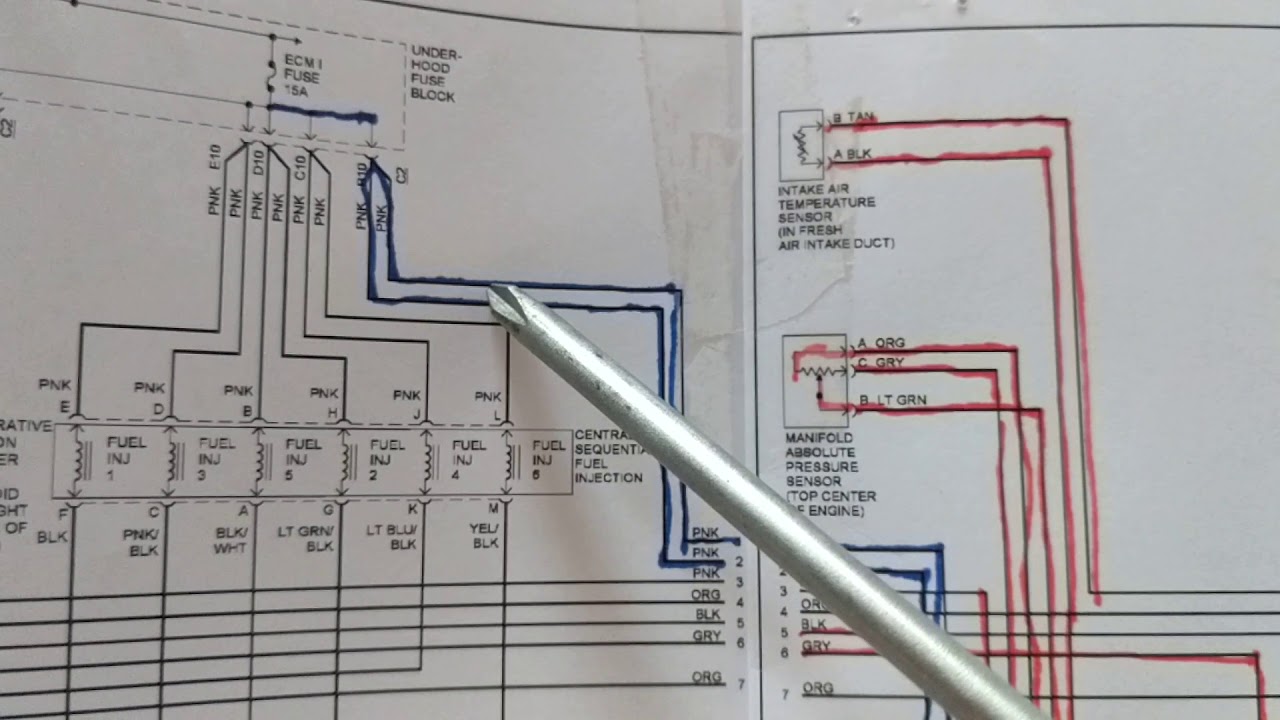
- Lines: Solid lines represent wires, while dashed lines may indicate shielding or connections within a component. Line thickness can sometimes indicate the wire gauge (thicker lines = thicker wires).
- Colors: Each wire is assigned a color code (e.g., RED, BLK, WHT/BLK). These codes are usually abbreviated. Match the colors on the diagram to the actual wires in your truck.
- Ground Symbols: These indicate where the circuit is grounded to the vehicle's chassis. Look for symbols that resemble an upside-down triangle or a series of horizontal lines decreasing in length.
- Connectors: Connectors are often represented by squares or rectangles with lines extending from them, indicating the wires that connect to the connector.
- Component Symbols: Each component (coil, sensor, ECM) has a specific symbol. Consult the diagram's legend for the meanings of these symbols.
- Numbers/Letters: These are used to identify specific wires, connectors, or terminals. Pay close attention to these markings, especially when troubleshooting.
Color coding is your friend. If the diagram indicates a blue wire, and you find a red wire connected to a particular pin, that's a red flag. Follow the color codes religiously.
How It Works: Ignition System Overview
Here's a simplified explanation of how the 4.3 Vortec ignition system operates:
- The CKP sensor sends a signal to the ECM indicating the crankshaft's position and speed.
- The CMP sensor identifies which cylinder is on its compression stroke.
- The ECM uses this information to determine the correct ignition timing.
- The ECM sends a low-voltage signal to the ICM.
- The ICM interprets this signal and switches the primary current flowing through the designated ignition coil(s) on and off.
- When the ICM cuts the primary current, the magnetic field in the ignition coil collapses.
- This collapsing magnetic field induces a very high-voltage in the secondary winding of the coil.
- This high-voltage is then sent to the spark plug, creating a spark that ignites the air-fuel mixture in the cylinder.
The beauty of the DIS system is that it eliminates the mechanical complexity of a distributor. The ECM handles the timing and firing of the coils electronically, resulting in more precise and reliable ignition.
Real-World Use: Troubleshooting Tips
Here are some common issues you might encounter and how the wiring diagram can help:
- Misfire: A misfire can be caused by a faulty ignition coil, a wiring problem, a bad spark plug, or other issues. The diagram helps you trace the wiring from the ECM to the coil to identify any breaks, shorts, or loose connections. A multimeter can be used to test for continuity and voltage at various points in the circuit.
- No-Start Condition: If your truck won't start, the ignition system could be to blame. Use the diagram to verify that the ECM is receiving signals from the CKP and CMP sensors. Check the power and ground connections to the ICM and coils.
- Erratic Engine Performance: Poor engine performance can sometimes be attributed to ignition timing problems. The diagram can help you verify the integrity of the wiring between the sensors, ECM, and ICM.
Always start with the basics: check the fuses and relays associated with the ignition system. A blown fuse can prevent the entire system from working. Check for corroded connectors. Use dielectric grease on connectors to prevent corrosion. A visual inspection often reveals obvious problems like frayed wires or melted connectors.
Safety Precautions
The ignition system involves high voltages, so safety is paramount.
- Disconnect the Battery: Always disconnect the negative battery cable before working on the ignition system. This will prevent accidental shocks and potential damage to electrical components.
- High-Voltage Components: Be extremely cautious when working near the ignition coils and spark plug wires. These components can deliver a painful and potentially dangerous electric shock.
- Capacitors: Ignition coils can store electrical charge even after the engine is turned off. Discharge the coils before handling them.
- Fuel System: Be aware of the proximity of fuel lines and components. Sparks can ignite fuel vapors. Work in a well-ventilated area.
Never work on the ignition system with the engine running unless you're using specialized diagnostic equipment designed for that purpose. Exercise extreme caution!
Conclusion
By understanding the ignition coil wiring diagram for your 4.3 Vortec Chevy Truck, you'll be well-equipped to diagnose and repair ignition system problems, perform modifications, and maintain your truck's performance. Remember to work safely, use the diagram as your guide, and don't hesitate to consult a professional mechanic if you're unsure about any aspect of the repair.
We have the wiring diagram file available for download to assist you further.