Chevy Truck Electrical Wiring Diagram
So, you’re ready to dive into the fascinating world of Chevy truck electrical systems. Whether you're tackling a frustrating electrical gremlin, planning a custom lighting upgrade, or simply want a deeper understanding of your vehicle, understanding the electrical wiring diagram is absolutely crucial. Think of it as the Rosetta Stone for your truck's nervous system – without it, you're fumbling in the dark. This article aims to equip you with the knowledge to read, interpret, and confidently use a Chevy truck electrical wiring diagram.
Purpose: Why Bother with Wiring Diagrams?
Why should you spend your time deciphering a complex schematic? The answer is simple: efficiency and accuracy. An electrical wiring diagram is your best friend for:
- Troubleshooting Electrical Issues: Pinpointing the exact location of a short circuit, open circuit, or faulty component becomes exponentially easier with a diagram. No more guessing and replacing parts at random.
- Performing Repairs: Whether it's replacing a damaged wire, repairing a connector, or rewiring a section of the harness, the diagram ensures you're making the correct connections.
- Adding Aftermarket Accessories: Installing fog lights, a new stereo, or any other electrical accessory requires tapping into the existing wiring. A diagram helps you identify the correct wires and avoid damaging your truck's electrical system.
- Understanding Your Truck: Even if you're not planning any immediate repairs, studying the wiring diagram provides a comprehensive overview of your truck's electrical architecture. This knowledge can be invaluable for future maintenance and modifications.
- Preventing Future Problems: By understanding how the electrical system is designed, you can identify potential weak points and take preventative measures to avoid future failures.
Key Specs and Main Parts: What You Need to Know
Before we delve into the specifics, let's cover some essential terms and components you'll encounter in a Chevy truck electrical wiring diagram:
- Voltage: The electrical potential difference, measured in volts (V). Most Chevy trucks operate on a 12V DC (Direct Current) system.
- Current: The flow of electrical charge, measured in amperes (amps or A). Understanding the current draw of different circuits is critical for choosing the correct wire gauge and fuses.
- Resistance: The opposition to the flow of current, measured in ohms (Ω). High resistance can indicate a corroded connection or a failing component.
- Ground: The reference point for all electrical circuits, typically the vehicle's chassis. A good ground connection is essential for proper operation.
- Fuses: Protective devices that interrupt the circuit if the current exceeds a safe level. They protect components from damage caused by short circuits or overloads.
- Relays: Electrically operated switches that control high-current circuits using a low-current signal. They're commonly used to control headlights, horns, and other high-power accessories.
- Switches: Devices that open or close an electrical circuit.
- Sensors: Devices that measure various parameters (e.g., temperature, pressure, speed) and convert them into electrical signals that the engine control unit (ECU) can use.
- Actuators: Devices that convert electrical signals into mechanical action (e.g., fuel injectors, solenoids).
- ECU (Engine Control Unit): The "brain" of the engine management system. It receives signals from sensors, processes the information, and controls actuators to optimize engine performance. Modern trucks also often have Body Control Modules (BCMs) that handle non-engine related electrical functions.
- Connectors: Devices that join wires together. They can be prone to corrosion and can cause electrical problems.
- Wiring Harness: A bundle of wires that are routed throughout the vehicle. They are often protected by a plastic sheath.
Symbols: Deciphering the Diagram's Language
Electrical wiring diagrams use a standardized set of symbols to represent different components and connections. Here are some of the most common symbols you'll encounter:
- Wires: Solid lines represent wires. Dashed lines often represent shielded wires. The color of the wire is usually indicated by a code adjacent to the line (e.g., RD for red, BK for black, GN for green).
- Grounds: Various symbols are used to represent ground connections, often resembling a series of stacked horizontal lines or a triangle pointing downwards.
- Fuses: A zig-zag line enclosed in a rectangle. The amperage rating is usually indicated next to the symbol.
- Relays: A coil symbol (representing the relay's electromagnet) and a switch symbol.
- Switches: A line that is either connected or disconnected to another line, depending on the switch's position.
- Resistors: A zig-zag line.
- Capacitors: Two parallel lines.
- Diodes: A triangle pointing towards a line.
- Connectors: Circles or squares where wires are joined together. These often have alphanumeric identifiers to help you locate the physical connector in the vehicle.
Understanding wire color codes is paramount. Common codes include: BK (Black), RD (Red), WH (White), GN (Green), BL (Blue), YL (Yellow), OR (Orange), BR (Brown), GY (Gray), VT (Violet/Purple). Sometimes, you'll see a combination, like WH/BK, indicating a white wire with a black stripe.
How It Works: Tracing the Circuit
A wiring diagram shows the path of electrical current through a circuit. To understand how a circuit works, start at the power source (usually the battery), follow the wire through the fuse, switch, relay (if applicable), and finally to the component it powers. Then, trace the return path back to ground. Always pay attention to the direction of current flow, which is conventionally from positive (+) to negative (-).
Imagine tracing the circuit for your headlights. You'd start at the battery, find the fuse for the headlights, follow the wire to the headlight switch, then to the headlights themselves, and finally back to ground. The diagram will clearly show all the components involved and how they're connected.
Real-World Use: Basic Troubleshooting Tips
Here's how you can use a wiring diagram to diagnose common electrical problems:
- No Power to a Component: Check the fuse first! If the fuse is good, use a multimeter to check for voltage at the component's power wire. If there's no voltage, trace the wire back to the switch, relay, and eventually to the fuse box, looking for breaks or loose connections.
- Component Stays On: This could indicate a short circuit to ground. Use the diagram to identify the possible locations of the short and inspect the wiring harness for damage. A stuck relay could also be the cause.
- Intermittent Problems: These are the trickiest to diagnose. Use the diagram to identify the circuit and then systematically check each connection and component for loose connections, corrosion, or damage. Temperature changes and vibrations can often trigger intermittent problems.
- Using a Multimeter: A multimeter is your best friend when troubleshooting electrical problems. It can measure voltage, current, and resistance, allowing you to pinpoint the location of faults. Learn how to use it safely and effectively!
Safety: Respect the Electricity
Working with electricity can be dangerous. Always follow these safety precautions:
- Disconnect the Battery: Before working on any electrical circuit, disconnect the negative (-) terminal of the battery. This will prevent accidental shorts and shocks.
- Use Insulated Tools: Use tools with insulated handles to protect yourself from electric shock.
- Be Careful Around the Airbag System: The airbag system contains explosive components. Consult the service manual before working near the airbag system. Accidental deployment can cause serious injury.
- Avoid Working in Wet Conditions: Water is a conductor of electricity, so avoid working on electrical systems in wet conditions.
- Don't Guess: If you're unsure about something, consult a qualified electrician.
- High-Risk Components: Be especially careful around the ECU, BCM, and airbag control module. These components are sensitive to static electricity and can be easily damaged. Handle them with care and follow the manufacturer's instructions.
Understanding and using a Chevy truck electrical wiring diagram empowers you to diagnose and repair electrical issues confidently. Remember to work safely, double-check your connections, and don't be afraid to ask for help when needed. With practice and patience, you'll become a master of your truck's electrical system.
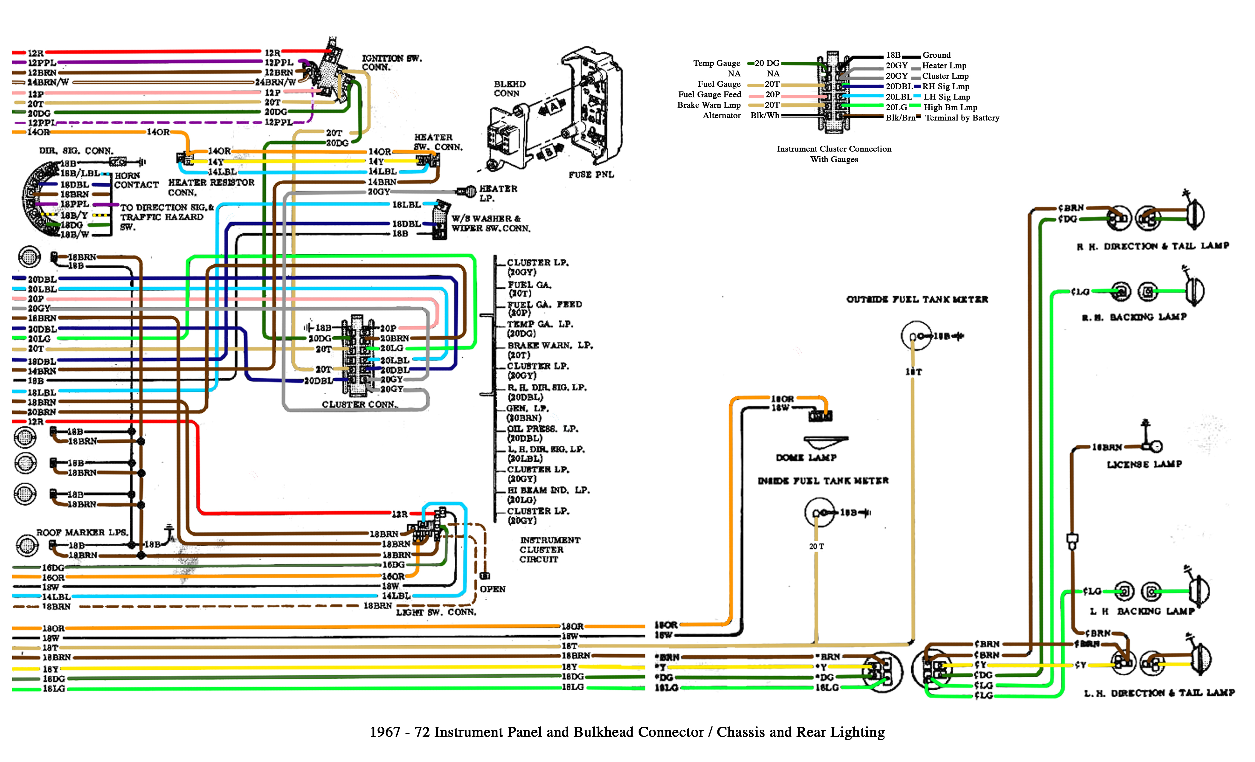
We have a sample Chevy Truck Electrical Wiring Diagram file available for download. This resource will provide you with a tangible example to practice reading and interpreting the information discussed in this article.