Chevy Truck Pinout Gm Instrument Cluster Wiring Diagram
The GM instrument cluster wiring diagram for Chevy trucks is an indispensable tool for anyone tackling electrical work on their vehicle. Whether you're diagnosing a malfunctioning gauge, upgrading your cluster, or performing a custom modification, understanding this diagram is crucial. This article will delve into the intricacies of the diagram, providing a clear and comprehensive guide for intermediate car owners, modders, and DIY mechanics.
Purpose of the GM Instrument Cluster Wiring Diagram
The instrument cluster wiring diagram serves several critical purposes:
- Troubleshooting: Pinpointing the source of electrical issues like a non-functional speedometer, fuel gauge, or warning light.
- Repair: Identifying damaged wires or connectors needing replacement or repair.
- Upgrades & Modifications: Installing aftermarket gauges, integrating new features (like shift lights or digital displays), or swapping in a different instrument cluster.
- Learning & Understanding: Gaining a deeper understanding of your vehicle's electrical system and how the instrument cluster interacts with other components.
Key Specs and Main Parts
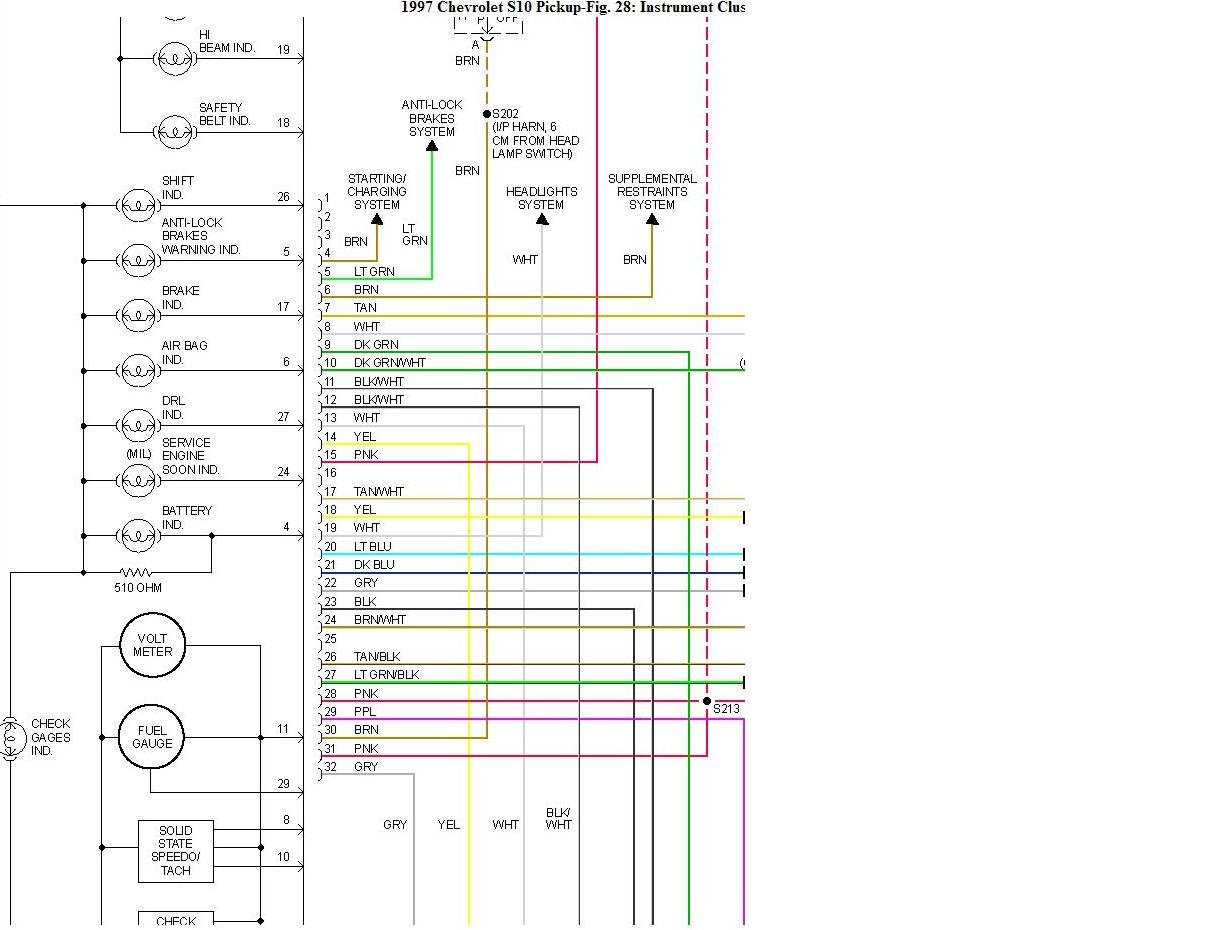
A typical GM instrument cluster wiring diagram, especially for trucks from the late '80s through the 2000s, will depict the following key components and their connections:
- Instrument Cluster Housing: The physical unit containing all the gauges and indicators.
- Gauges: Including the speedometer, tachometer, fuel gauge, oil pressure gauge, coolant temperature gauge, and voltmeter (ammeter in older models). These operate based on signals received from various sensors and the vehicle's computer (PCM/ECM).
- Warning Lights: Indicators for low fuel, check engine light (MIL - Malfunction Indicator Lamp), brake warning, airbag, security system, and other critical systems. These lights are generally controlled by the PCM/ECM or other control modules.
- Connectors: Multi-pin connectors that plug into the back of the instrument cluster, providing power, ground, and signal inputs/outputs. The diagram will specify the pin assignments for each connector.
- Printed Circuit Board (PCB): The circuit board inside the cluster that connects all the components.
- Dimmer Switch: Controls the brightness of the instrument cluster illumination.
- Grounding Points: Designated locations where the cluster connects to the vehicle's chassis ground. Good grounding is essential for proper operation.
Symbols and Conventions
Understanding the symbols used in the wiring diagram is essential for interpreting the information correctly. Here's a breakdown of common symbols:
- Lines: Represent wires. A solid line typically indicates a continuous wire, while a dashed line may indicate a connection through a connector or splice. The thickness of the line does NOT usually indicate wire gauge.
- Colors: Wires are color-coded. The diagram will use abbreviations for colors (e.g., "RED," "BLK," "WHT," "GRN," "BLU," "YEL"). Sometimes a wire will have a primary color and a secondary color (e.g., "GRN/WHT" – Green wire with a White stripe).
- Connectors: Usually represented by a box or rectangle with pins numbered. The diagram will show which wire color connects to each pin.
- Ground Symbols: Represent a connection to the vehicle's chassis ground. Different ground symbols exist, but they all indicate a connection to the metal body of the vehicle.
- Splice Points: Represent locations where multiple wires are joined together.
- Components: Each gauge, light, and switch will have a specific symbol. These are often simplified representations of the actual component.
- Resistors, Capacitors, Diodes: If these are present in the cluster's circuitry (common in newer, more complex clusters), they will be represented by their standard electronic symbols.
How It Works: A Systems Overview
The instrument cluster receives data from various sensors and control modules throughout the vehicle. This data is then processed and displayed on the gauges and indicators.
- Power and Ground: The cluster needs a constant 12V power supply and a reliable ground connection to operate.
- Sensor Signals: Sensors such as the vehicle speed sensor (VSS), fuel level sender, oil pressure sensor, and coolant temperature sensor send analog or digital signals to the cluster.
- PCM/ECM Communication: Modern vehicles often use a Controller Area Network (CAN) bus to transmit data between the PCM/ECM and the instrument cluster. This allows for more efficient communication and the display of data that is calculated by the PCM/ECM, such as engine RPM and vehicle speed. Older systems might use direct wiring for some signals.
- Gauge Operation: The cluster processes the incoming signals and uses them to control the movement of the gauge needles. Older gauges were often electromagnetic, relying on coils and magnetism. Newer gauges are often stepper motor-driven, providing more precise control.
- Warning Light Activation: The PCM/ECM or other control modules can activate warning lights based on various conditions. For example, if the engine coolant temperature is too high, the PCM will activate the temperature warning light.
Real-World Use: Basic Troubleshooting Tips
Here are some basic troubleshooting tips using the wiring diagram:
- No Power to Cluster: Check the power and ground connections to the cluster. Use a multimeter to verify that you have 12V at the power pin and a good ground connection. Also, check the fuses associated with the instrument cluster.
- Gauge Not Working: Identify the wire that carries the signal from the sensor to the gauge. Use a multimeter to check the signal voltage or resistance. If the signal is missing, the problem could be with the sensor, the wiring, or the PCM/ECM (if the signal is transmitted via the CAN bus).
- Warning Light Stays On: Use a scan tool to retrieve diagnostic trouble codes (DTCs) from the PCM/ECM. The DTCs will help you pinpoint the cause of the problem. Consult the wiring diagram to trace the wiring associated with the affected sensor or circuit.
- Dim or Flickering Lights: Check the ground connections to the cluster and the dimmer switch. A poor ground can cause dim or flickering lights.
Example Scenario: Your speedometer isn't working. Refer to the wiring diagram to identify the VSS signal wire. Use a multimeter to check for a signal while the vehicle is moving (safely!). If there's no signal, inspect the VSS itself, the wiring between the VSS and the cluster, and the connector at the cluster. If the VSS signal goes to the PCM first, you'll need to check the CAN bus communication or the wire from the PCM to the cluster.
Safety Considerations
Working on automotive electrical systems can be dangerous. Take the following precautions:
- Disconnect the Battery: Always disconnect the negative battery cable before working on any electrical components. This prevents accidental shorts and potential damage to the vehicle's electrical system.
- Airbags: Be extremely cautious when working near airbags. Accidental activation of an airbag can cause serious injury. Consult the vehicle's service manual for specific instructions on disabling the airbag system. Do not probe airbag connectors directly with a multimeter.
- Fuel System: Be aware of fuel lines and components. Avoid creating sparks or using open flames near the fuel system.
- Tools: Use insulated tools to prevent electrical shock.
- Proper Testing: Use a multimeter or test light to safely check for voltage and continuity. Never use a test light to probe sensitive electronic components like ECUs or sensors. This can cause damage.
High-Risk Components: The airbag system and fuel system are particularly risky. If you're not comfortable working on these systems, it's best to consult a qualified technician.
The GM instrument cluster wiring diagram is an essential resource for diagnosing and repairing electrical problems in your Chevy truck. By understanding the symbols, components, and how the system works, you can confidently tackle a wide range of electrical projects. Always prioritize safety and consult the vehicle's service manual for specific instructions and warnings.
We have access to a comprehensive collection of GM instrument cluster wiring diagrams. Please contact us to download the specific diagram relevant to your Chevy truck model and year.