
Chevy Truck Tail Light Wiring Diagram
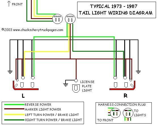
Understanding your Chevy truck's tail light wiring diagram is crucial, whether you're tackling a simple bulb replacement, diagnosing a frustrating lighting issue, or even planning a custom modification. This isn't just about knowing which wire goes where; it's about understanding the entire electrical circuit, its components, and how they interact. This guide will break down the intricacies of a typical Chevy truck tail light wiring diagram, giving you the knowledge to confidently troubleshoot and repair your truck's rear lighting system.
Purpose: Why You Need to Understand the Diagram
A tail light wiring diagram is more than just a road map for your truck's rear lights; it's a diagnostic tool, a modification guide, and a key to preventative maintenance. Here's why you should familiarize yourself with it:
- Troubleshooting Electrical Problems: Tail lights, brake lights, and turn signals are critical for safety. A wiring diagram helps you pinpoint the source of a malfunction, whether it's a blown fuse, a faulty ground, or a damaged wire. Without it, you're just guessing.
- Performing Repairs and Replacements: Need to replace a damaged tail light assembly? The diagram shows you exactly how to disconnect and reconnect the wiring correctly.
- Installing Aftermarket Accessories: Planning to add a trailer hitch with integrated lighting, LED tail lights, or a custom bed light? The wiring diagram guides you in tapping into the correct circuits safely and effectively.
- Understanding the Electrical System: Even if you're not experiencing problems, studying the diagram provides a deeper understanding of your truck's electrical system, which can be beneficial for future maintenance and upgrades.
Key Specs and Main Parts
Let's define the main components you'll find in a typical Chevy truck tail light wiring diagram. These components work together to ensure your tail lights function correctly.
- Battery: The heart of the electrical system, providing the necessary DC voltage (typically 12V) to power the lights.
- Fuse Box: Contains fuses (and sometimes circuit breakers) that protect individual circuits from overloads. A blown fuse is often the first indication of a problem. Check the fuse box for the *tail light fuse*, the *brake light fuse*, and the *turn signal fuse*.
- Wiring Harness: A bundle of wires that connects the various components of the tail light system. Each wire is typically color-coded for easy identification.
- Light Switch/Headlight Switch: Controls the activation of the tail lights when the headlights are turned on.
- Brake Light Switch: Activated when the brake pedal is pressed, sending power to the brake lights. Located near the brake pedal assembly.
- Turn Signal Switch (Multi-Function Switch): Located on the steering column, controls the left and right turn signals.
- Turn Signal Flasher: A device that interrupts the current to the turn signal lights, causing them to flash.
- Tail Light Assembly: The physical housing containing the bulbs for the tail lights, brake lights, and turn signals.
- Bulbs: Incandescent or LED bulbs that provide the illumination. Common bulb types include 1157 (dual filament) and 3157.
- Ground Connection: A critical connection that provides a return path for the electrical current. A poor ground connection can cause various lighting problems.
Symbols: Deciphering the Diagram
Wiring diagrams use specific symbols and conventions to represent electrical components and connections. Understanding these symbols is essential for interpreting the diagram accurately.
- Lines: Represent wires. Solid lines typically indicate a direct connection, while dashed lines may indicate a connection that is only active under certain conditions. Wire thickness may sometimes be indicated to denote the wire's gauge (its current-carrying capacity).
- Color Codes: Wires are typically color-coded to aid in identification. Common color codes include:
- Black (BLK): Ground
- Red (RED): Power from the battery
- Brown (BRN): Tail lights
- Green (GRN): Right turn signal and brake light
- Yellow (YEL): Left turn signal and brake light
- White (WHT): Often used for ground or backup lights
Note: Color codes can vary depending on the year and model of your Chevy truck. Always consult the specific wiring diagram for your vehicle.
- Circles: Represent electrical connections or junctions.
- Rectangles: Represent switches or relays.
- Zigzag Lines: Represent resistors or other components that impede the flow of current.
- Ground Symbol: A symbol that looks like a series of horizontal lines connected to a vertical line, indicating a connection to the vehicle's chassis (ground). A good ground connection is crucial for proper circuit operation.
How It Works: Following the Circuit
The Chevy truck tail light circuit is a relatively simple system, but understanding how each component interacts is key to troubleshooting. Here's a simplified overview:
- Tail Lights: When the headlight switch is activated, it sends power through a fuse to the tail light circuit. This power flows through the brown wire to the tail light bulbs, illuminating them.
- Brake Lights: When the brake pedal is pressed, the brake light switch closes, sending power through a separate fuse to the brake light circuit. This power flows through the green and yellow wires to the brake light filaments within the 1157 bulbs (or to the dedicated brake light bulbs in some models), illuminating them brightly.
- Turn Signals: When the turn signal lever is activated, it sends power through the turn signal flasher to the appropriate turn signal circuit (left or right). The flasher interrupts the current, causing the turn signal bulbs (also using the green and yellow wires in conjunction with the brake light filaments) to flash on and off.
- Ground: All circuits require a return path to the battery. This is provided by the ground connection, which connects the tail light assembly (and other components) to the vehicle's chassis. A poor ground can cause dim lights, flickering, or complete failure of the circuit. Poor grounding is a very common cause of electrical problems in vehicles!
Real-World Use: Basic Troubleshooting Tips
Here are some common tail light problems and how to use the wiring diagram to troubleshoot them:
- No Tail Lights:
- Check the tail light fuse in the fuse box. Replace if blown.
- Verify that the headlight switch is functioning correctly.
- Check the ground connection at the tail light assembly. Clean and tighten if necessary.
- Use a multimeter to check for voltage at the tail light bulb socket when the headlights are turned on. If no voltage is present, trace the wiring back to the headlight switch and fuse box.
- No Brake Lights:
- Check the brake light fuse in the fuse box. Replace if blown.
- Verify that the brake light switch is functioning correctly. You can usually test this with a multimeter.
- Inspect the wiring from the brake light switch to the tail light assembly for damage.
- Check the bulbs themselves – are both filaments working (assuming a dual-filament bulb)?
- No Turn Signals:
- Check the turn signal fuse in the fuse box. Replace if blown.
- Verify that the turn signal flasher is functioning correctly. You can often hear a clicking sound when it's working.
- Check the turn signal switch on the steering column.
- Inspect the wiring from the turn signal switch to the tail light assembly for damage.
- Dim Lights or Flickering: This is often a sign of a poor ground connection. Clean and tighten all ground connections in the tail light circuit.
Safety: Working with Electrical Components
Working with automotive electrical systems can be dangerous. Always take the following precautions:
- Disconnect the Battery: Before working on any electrical component, disconnect the negative (-) terminal of the battery to prevent short circuits and electrical shocks.
- Use a Multimeter: A multimeter is an essential tool for diagnosing electrical problems. Learn how to use it to test for voltage, continuity, and resistance.
- Avoid Water: Never work on electrical components in wet conditions.
- Be Careful with Wiring: Handle wiring carefully to avoid damaging insulation or creating short circuits.
- Replace Damaged Wiring: Replace any damaged or frayed wiring immediately.
- Fuses are Important!: Never bypass a fuse or replace it with one of a higher amperage rating. Fuses protect the circuit from overloads and prevent fires.
Remember that some circuits, especially those related to airbags or ABS, can store energy even after the battery is disconnected. Consult your vehicle's repair manual for specific safety precautions before working on these systems.
By understanding the principles outlined in this guide and carefully studying your Chevy truck's tail light wiring diagram, you'll be well-equipped to tackle most common lighting issues. Happy wrenching!
We have a downloadable copy of a generic Chevy truck tail light wiring diagram readily available. Please note that wiring diagrams can vary significantly based on the year, make, and model of your truck. Always consult the specific wiring diagram for your vehicle for the most accurate information. We are not responsible for any damages caused by using the wrong diagram.