
Chevy Truck Trailer Wiring Color Code
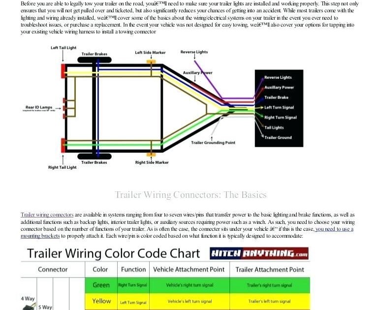
Understanding the Chevy truck trailer wiring color code is essential for any DIY mechanic, modder, or truck owner who wants to safely and effectively connect a trailer. Whether you're tackling trailer light repairs, installing a new trailer brake controller, or just learning the electrical system of your Chevy truck, knowing how the wiring works is paramount. This article will break down the standard color code, explaining its purpose, key components, and offering real-world troubleshooting tips.
Purpose of Understanding Trailer Wiring
Why bother learning this? Imagine needing to replace a damaged trailer connector on the side of the road. Without understanding the color code, you're left guessing, potentially causing shorts, blown fuses, or even damaging your truck's electrical system. A solid understanding of trailer wiring enables you to:
- Diagnose and repair trailer light issues: Identify breaks in the circuit, bad grounds, or faulty lights.
- Install trailer brake controllers: Properly connect the controller to your truck's brake system and trailer brakes.
- Connect auxiliary trailer functions: Power additional trailer accessories like interior lights or a winch.
- Ensure safe towing: Properly functioning trailer lights are critical for visibility and signaling, preventing accidents.
Ultimately, knowing your Chevy truck's trailer wiring color code saves you time, money, and potential headaches on the road.
Key Specs and Main Parts
The standard trailer wiring connector for most light- to medium-duty Chevy trucks is the 7-way RV blade connector. While variations exist, this is the most common and the one we'll focus on. The core system comprises:
- Truck-Side Connector: This is the receptacle on your Chevy truck that accepts the trailer plug.
- Trailer-Side Connector: This is the plug on your trailer that connects to the truck.
- Wiring Harness: The bundle of wires connecting the connector to the truck's electrical system.
- Fuses and Relays: These protect the wiring and components from overloads and provide switching power. These are critical for safety.
- Trailer Brake Controller (if equipped): Manages the electric trailer brakes.
Key Specs to Note:
- Voltage: The system operates primarily on 12V DC.
- Amperage: Each circuit is rated for a specific amperage. Exceeding this can blow fuses. Refer to your truck's owner's manual or the trailer wiring diagram for specific ratings.
- Wire Gauge: The thickness of the wire (gauge) determines how much current it can safely handle. Heavier gauge wires are used for high-current circuits like trailer brakes.
Symbols and Color Code Explanation
Understanding the color code and associated symbols is the heart of this knowledge. Here's a breakdown of the 7-way RV blade connector and its standard color assignments:
- White (Ground): The most important wire! Provides the return path for all electrical circuits. Often connected to the trailer frame. Symbol: Typically shown as a ground symbol (three horizontal lines descending in length).
- Yellow (Left Turn/Brake): Controls the left turn signal and brake light on the trailer. Symbol: Often labeled "LT" or shown with an arrow pointing left.
- Green (Right Turn/Brake): Controls the right turn signal and brake light on the trailer. Symbol: Often labeled "RT" or shown with an arrow pointing right.
- Brown (Tail/Running Lights): Powers the taillights, side marker lights, and license plate light on the trailer. Symbol: Often labeled "TL" or "Tail".
- Blue (Electric Brakes): Activates the electric brakes on the trailer. This wire connects to the trailer brake controller. Symbol: Often labeled "EB" or "Brakes".
- Red (Auxiliary Power/Battery Charge): Provides a 12V DC power supply to the trailer, often used to charge the trailer battery or power interior lights. Symbol: Often labeled "AUX" or "BAT". This wire should be properly fused near the truck battery.
- Black (12V Power Supply): Provides a fused 12V DC power supply to the trailer, often used to power interior lights or other accessories. Symbol: Typically shown as "+12V". This is often used to charge the trailer battery and should also be properly fused.
Diagram Interpretation: In a wiring diagram, wires are typically represented by solid lines. Different colors indicate the function of each wire as described above. Connection points are shown as dots or circles where lines intersect. Symbols for lights (usually circles with an "X" inside) and other components are used to illustrate the circuit layout.
How It Works: A Basic Circuit Explanation
The trailer wiring system functions as a series of electrical circuits. Each circuit requires a power source, a load (the light or brake), and a return path (ground). Here's a simplified explanation of how a brake light circuit works:
- When you press the brake pedal in the truck, a signal is sent to the brake light switch.
- This signal triggers the truck's brake light circuit, sending 12V DC power to the brake lights on the truck AND to the yellow (left) and green (right) wires in the trailer connector.
- The power travels through the yellow/green wire to the corresponding brake lights on the trailer.
- The brake lights illuminate.
- The current returns to the truck through the white (ground) wire, completing the circuit.
A similar process occurs for the turn signals and tail lights. The trailer brake controller, when activated, sends a variable voltage signal through the blue wire to activate the trailer brakes proportionally to the truck's braking force. Proper grounding is absolutely crucial for all circuits to function correctly. A bad ground can cause dim lights, erratic brake function, or complete circuit failure.
Real-World Use: Basic Troubleshooting Tips
Here are some common problems and troubleshooting steps:
- No Trailer Lights: Check the truck-side fuse for the trailer lights. Inspect the trailer-side connector for corrosion or damage. Test the ground connection. Use a multimeter to check for voltage at the trailer connector when the lights should be on.
- Dim Trailer Lights: Suspect a bad ground connection. Clean and tighten the ground connections on both the truck and trailer. Check for corrosion on the light bulb sockets.
- One Turn Signal Not Working: Check the bulb. Test for voltage at the connector. Inspect the wiring for breaks or shorts.
- Trailer Brakes Not Working: Verify the trailer brake controller is properly adjusted. Check the blue wire connection. Inspect the trailer brake magnets for damage.
Tools You'll Need:
- Multimeter
- Test Light
- Wire Strippers/Crimpers
- Electrical Tape or Heat Shrink Tubing
- Screwdrivers
Safety Considerations
Working with electrical systems can be dangerous. Always disconnect the negative battery terminal before working on any electrical components. Be especially cautious when working with the auxiliary power (red) and 12V power (black) wires, as they carry a constant 12V DC supply. Ensure these circuits are properly fused to prevent short circuits and potential fires. Never exceed the amperage rating of the wiring or fuses. When splicing wires, use proper connectors and ensure a secure, weatherproof connection. Poor connections can cause resistance, heat, and ultimately, failure.
Important Safety Note: If you are not comfortable working with electrical systems, consult a qualified mechanic. Incorrect wiring can damage your truck, trailer, or even cause a fire.
We have a detailed Chevy Truck Trailer Wiring Diagram available for download. This diagram provides a visual representation of the wiring system, including wire colors, component locations, and circuit layouts. It's a valuable resource for any DIY mechanic.