
Chevy Turn Signal Switch Wiring Diagram
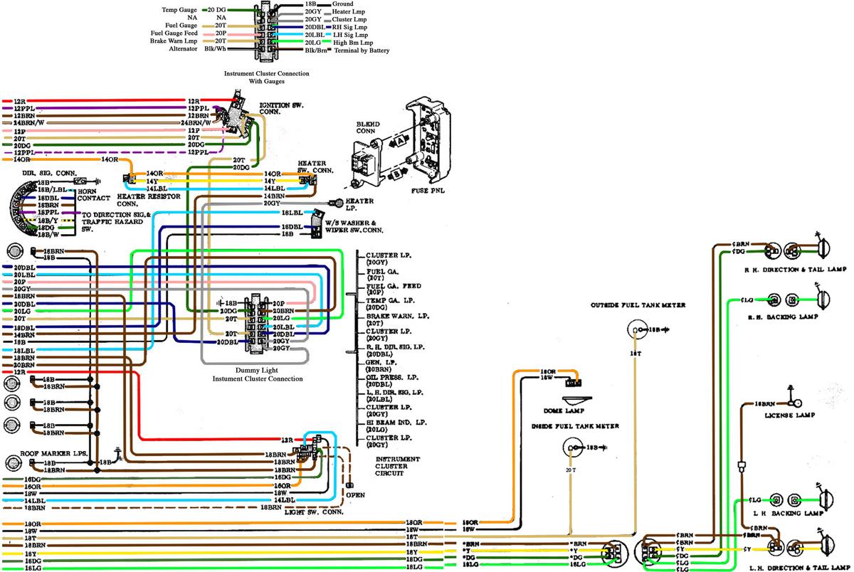
Understanding your Chevy's turn signal switch wiring diagram is crucial for a variety of reasons, ranging from simple bulb replacements to more complex electrical troubleshooting or even custom modification projects. Whether you're dealing with a malfunctioning turn signal, adding aftermarket lights, or just expanding your automotive knowledge, this guide will equip you with the necessary information to navigate the intricacies of your Chevy's turn signal system.
Purpose of the Wiring Diagram
A turn signal switch wiring diagram is a visual representation of the electrical connections within the turn signal system. It illustrates how the various components are interconnected, providing a roadmap for diagnosing problems and performing repairs. Its primary uses include:
- Troubleshooting Electrical Issues: Pinpointing shorts, opens, and other faults within the turn signal circuit.
- Performing Repairs: Replacing damaged wires, switches, or other components.
- Adding Aftermarket Accessories: Integrating new lights, alarms, or other electrical devices into the existing system.
- Understanding System Operation: Gaining a deeper understanding of how the turn signal system works.
Key Specifications and Main Parts
Before diving into the diagram itself, let's review the key components and specifications you'll encounter in a typical Chevy turn signal system. Note that specific wiring configurations can vary depending on the year, make, and model of your Chevy.
Main Components:
- Turn Signal Switch: The central control point for activating the turn signals, hazard lights, and often the high beam headlights. It's typically located on the steering column.
- Flasher Unit (or Relay): An electronic or electromechanical device that causes the turn signal lights to blink on and off. Modern vehicles often use a solid-state flasher integrated into the body control module (BCM).
- Turn Signal Bulbs: The lights themselves, located at the front and rear of the vehicle. These are typically incandescent or LED bulbs.
- Hazard Light Switch: A separate switch, often located on the dashboard, that activates all turn signal lights simultaneously.
- Wiring Harness: A bundle of wires that connects all the components of the turn signal system.
- Fuse: A safety device that protects the circuit from overcurrent. A blown fuse is a common cause of turn signal failure.
- Ground Connection: The return path for the electrical current, typically connected to the vehicle's chassis.
Typical Wire Gauges and Colors:
Wire gauges (thickness) and colors are crucial for identifying wires in the harness. While standardization exists to some extent, always verify with your specific wiring diagram. Common wire colors include:
- Dark Green: Right turn signal.
- Light Green: Left turn signal.
- White/Brown (or Brown): Parking lights/Tail lights.
- Purple: Brake light circuit.
- Black: Ground.
- Pink: Ignition.
- Yellow: Hazard flasher feed.
Typical wire gauges for turn signal circuits range from 16 to 18 AWG (American Wire Gauge). Heavier gauges (lower numbers) can be used for circuits carrying more current.
Symbols – Decoding the Diagram
Wiring diagrams utilize standard symbols to represent electrical components and connections. Understanding these symbols is key to interpreting the diagram accurately.
Lines:
- Solid Lines: Represent wires. The thickness of the line doesn't necessarily indicate wire gauge.
- Dashed Lines: May represent shielded wires or connections that are only active in certain modes.
- Arrows: Indicate the direction of current flow.
Colors:
Colors are often indicated by abbreviations or color codes next to the wires in the diagram. Refer to the diagram's legend for the specific color codes used.
Icons:
- Resistor: A zigzag line.
- Capacitor: Two parallel lines.
- Diode: A triangle pointing to a vertical line.
- Ground: A series of descending horizontal lines or an inverted triangle.
- Fuse: A squiggly line inside a rectangle.
- Switch: A line bridging two or more other lines, often with a lever indicating the switch position.
- Bulb: A circle with an "X" inside.
- Connector: A circle, square, or other shape indicating a point where wires are connected together.
A key element is understanding the concept of "node". A node is a point in the circuit where multiple wires connect. These are often represented by filled circles in the diagram. If a node is not properly connected, it can cause a variety of problems.
How It Works
The turn signal system operates by selectively routing power from the battery (via the ignition switch) through the flasher unit and then to the appropriate turn signal bulbs. When the turn signal switch is activated (left or right), it completes a circuit, allowing the flasher unit to pulse the power to the selected lights. The flasher unit contains a bi-metallic strip or a solid-state circuit that heats up when current flows through it, causing it to bend and break the circuit, then cool down and reconnect it, creating the blinking effect. The hazard light switch operates similarly, but it activates both the left and right turn signal circuits simultaneously.
Real-World Use – Basic Troubleshooting Tips
Here are a few basic troubleshooting steps you can take using the wiring diagram:
- Check the Fuses: The simplest and most common cause of turn signal failure is a blown fuse. Locate the fuse for the turn signal system (refer to your owner's manual) and inspect it. Replace it if it's blown.
- Inspect the Bulbs: A burnt-out bulb will prevent the turn signal from working on that side. Replace any faulty bulbs.
- Test the Flasher Unit: If the turn signals don't blink at all, the flasher unit may be faulty. You can usually test the flasher unit by replacing it with a known good one. (Modern vehicles: consider a scan tool to diagnose BCM functionality).
- Check the Wiring Connections: Inspect the wiring harness and connectors for loose connections, corrosion, or damaged wires. Use a multimeter to check for continuity and voltage at various points in the circuit.
- Isolate the Switch: If other functions on the switch (e.g., high beams) are working, but turn signals aren't, focus on the turn signal-specific parts of the switch.
Example: If only the left turn signal is not working, consult the wiring diagram to trace the circuit for the left turn signal. Check the wire connection from the turn signal switch to the left turn signal bulb. If there is no voltage at the bulb socket, check the continuity of the wire. If the wire is intact, the problem may be the turn signal switch.
Safety – Highlighting Risky Components
Working with automotive electrical systems can be dangerous. Always take the following precautions:
- Disconnect the Battery: Before working on any electrical components, disconnect the negative battery cable to prevent accidental shorts and electrical shocks.
- Use Proper Tools: Use insulated tools designed for automotive electrical work.
- Avoid Working in Wet Conditions: Water can conduct electricity and increase the risk of shock.
- Be Careful with Airbags: Many turn signal switches are located near the airbag module. Handle the airbag module with care and follow the manufacturer's instructions to avoid accidental deployment. Accidental airbag deployment can cause serious injury!
- Double-Check Your Work: Before reconnecting the battery, double-check all connections to ensure they are secure and properly insulated.
Disclaimer: Automotive electrical systems can be complex. If you're not comfortable working on your vehicle's electrical system, it's best to consult a qualified mechanic.
We have a comprehensive Chevy Turn Signal Switch Wiring Diagram file available for download. This detailed diagram can be a valuable resource for your troubleshooting and repair needs. Feel free to download and use it as a reference. Remember to always prioritize safety when working with electrical systems. Happy wrenching!