Club Car Parts Diagram Front End
So, you're looking to dive into the front end of your Club Car? Smart move. Understanding the front end, and especially its diagram, is crucial for everything from routine maintenance to serious modifications. Think of this article as your roadmap to conquering your Club Car's steering and suspension. This isn't just about fixing a squeaky wheel; it’s about knowing your machine inside and out, leading to safer operation and preventing costly repairs down the line. We'll walk through the diagram, explain the key components, and give you some real-world troubleshooting tips. Plus, we have the actual diagram file ready for you to download - a handy reference you can keep by your side in the garage!
Purpose of a Club Car Front End Diagram
Why bother with a diagram at all? Well, the front end of your Club Car is a complex assembly of interconnected parts. The diagram serves several vital purposes:
- Repair and Maintenance: The most obvious use. When something breaks – a worn-out ball joint, a bent tie rod – the diagram allows you to accurately identify the part, its location, and how it connects to other components.
- Troubleshooting: Diagnosing problems is much easier with a visual aid. A diagram helps you trace issues from symptom to source, eliminating guesswork.
- Modifications and Upgrades: Planning a lift kit installation? Upgrading to disc brakes? The diagram shows you the layout and potential compatibility issues before you even turn a wrench.
- Understanding Assembly: Even if you don't plan on immediate repairs, studying the diagram provides a fundamental understanding of how the front end works. This is invaluable for preventative maintenance and spotting potential problems early.
Key Specs and Main Parts of Club Car Front End
Let's break down the major players in the front-end drama. Keep in mind that specific designs can vary slightly between Club Car models (DS, Precedent, Onward, etc.), but the core components remain largely the same.
Main Parts:
- Spindle (or Knuckle): The heart of the steering system. This component houses the wheel bearings and allows the wheel to pivot for steering. Think of it as the swivel point.
- Wheel Bearings: These allow the wheels to rotate smoothly on the spindle. Worn bearings cause noise and can lead to wheel wobble.
- Hub: The hub attaches the wheel to the spindle and transmits rotational force.
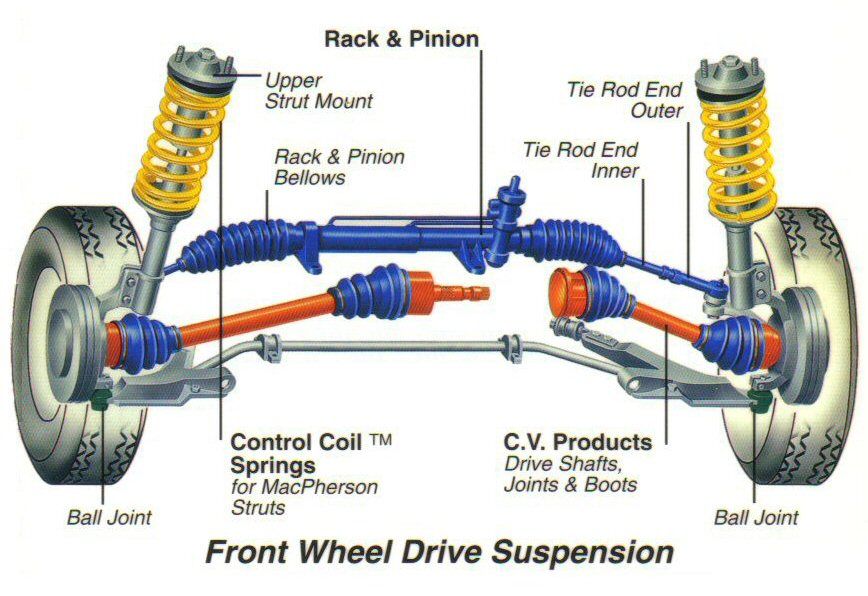
- Tie Rods: Connect the steering gear to the spindles. These rods transfer the steering input from the steering wheel to the wheels, causing them to turn.
- Tie Rod Ends: These are the ball-and-socket joints that connect the tie rods to the spindles and steering gear. They allow for movement and articulation in the steering system. These are wear items and common sources of looseness.
- Steering Gear (or Steering Box): This mechanism translates the rotary motion of the steering wheel into linear motion to move the tie rods. It often uses a worm gear or similar reduction to provide mechanical advantage.
- Steering Column: Connects the steering wheel to the steering gear.
- A-Arms (or Control Arms): These suspension components connect the spindle to the chassis. They allow the suspension to move up and down while maintaining proper wheel alignment. Club Cars often use an independent front suspension (IFS) with upper and lower A-arms.
- Ball Joints: Allow the A-arms to move up and down and pivot for steering. Like tie rod ends, these are wear items.
- Shocks (or Dampers): Control the movement of the suspension, preventing excessive bouncing and providing a smoother ride.
- Springs: Support the weight of the vehicle and absorb bumps. Coil springs are most common on Club Cars.
Key Specs:
- Toe: Refers to the angle of the wheels relative to each other. Positive toe (toe-in) means the front of the wheels are closer together than the rear. Negative toe (toe-out) is the opposite. Proper toe is critical for tire wear and handling.
- Camber: The angle of the wheel relative to the vertical axis. Positive camber means the top of the wheel is tilted outwards. Negative camber is the opposite. Excessive camber can cause uneven tire wear.
- Caster: The angle of the steering axis relative to the vertical axis, viewed from the side. Positive caster helps with straight-line stability.
These angles are critical to vehicle handling and tire wear. They are typically adjusted by adjusting the tie rod length or using shims on the A-arms.
Symbols on the Diagram
Understanding the symbols on the diagram is essential for interpreting it correctly. While specific diagrams may vary slightly, here are some common conventions:
- Lines: Solid lines generally represent physical components. Dashed lines might indicate hidden components or internal passages (like brake lines within a caliper).
- Arrows: Indicate direction of movement or flow (e.g., steering input direction, fluid flow).
- Circles/Ovals: Often used to represent fasteners like bolts, nuts, and washers. The size and shading can sometimes indicate the fastener size and material.
- Different Line Weights/Colors: These can distinguish between different systems. For example, thicker lines might represent structural components, while thinner lines represent fluid lines. Color coding might distinguish between brake lines, hydraulic lines, or electrical wires.
- Abbreviations: Be familiar with common abbreviations like "LH" (Left Hand), "RH" (Right Hand), "Frt" (Front), "Rr" (Rear), "Torq" (Torque).
Always refer to the diagram's legend (if available) for specific symbol definitions.
How It Works
Here's a simplified overview of how the Club Car front end operates:
- The driver turns the steering wheel.
- The steering column transmits this rotation to the steering gear.
- The steering gear converts the rotary motion into linear motion, moving the tie rods.
- The tie rods, connected to the spindles via tie rod ends, cause the spindles (and thus the wheels) to pivot.
- As the wheels encounter bumps, the suspension (A-arms, springs, and shocks) absorb the impact, providing a smoother ride. The A-arms allow the wheels to move up and down while maintaining alignment. The springs support the weight, and the shocks dampen the motion.
Real-World Use: Basic Troubleshooting
Let's say you're experiencing some common front-end issues:
- Wandering Steering: The vehicle doesn't track straight and requires constant steering correction. Possible causes include worn tie rod ends, loose ball joints, or incorrect toe alignment. Use the diagram to locate and inspect these components for play.
- Excessive Tire Wear: Uneven tire wear can indicate alignment problems (toe, camber, or caster). The diagram won't fix the alignment, but it will help you identify the components used to adjust it (typically tie rod ends).
- Clunking Noise: A clunking noise, especially over bumps, could indicate worn ball joints, loose A-arm bushings, or a damaged shock absorber. Again, the diagram helps you pinpoint the source of the noise. Pay close attention to the ball joints, as they often have grease fittings – lack of lubrication can accelerate wear.
- Squeaking Noise: Squeaks often come from dry ball joints, tie rod ends, or A-arm bushings. Try lubricating these components with a grease gun. The diagram shows you where the grease fittings are located (if applicable).
Pro Tip: When troubleshooting, always start with the simplest and most common causes first. Check tire pressure, look for obvious damage, and then move on to more complex diagnostics.
Safety – Highlight Risky Components
Working on the front end can be risky if you're not careful. Some key safety considerations:
- Springs: Compressed springs store a tremendous amount of energy. Never disassemble a suspension system without using proper spring compressors. Releasing a compressed spring without control can cause serious injury or death.
- Jacking and Support: Always use a properly rated jack and jack stands when lifting the vehicle. Never work under a vehicle supported only by a jack.
- Brake Lines: Be extremely careful when working near brake lines. Damaging a brake line can lead to brake failure. Always use the correct wrenches to avoid rounding off fittings.
- Torque Specifications: Always tighten fasteners to the manufacturer's specified torque. Over-tightening can damage components, while under-tightening can lead to loosening and failure. The repair manual or diagram often provides torque specifications.
- Wheel Removal: Always ensure the vehicle is stable and properly supported before removing a wheel.
Important: If you're unsure about any aspect of the repair, consult a qualified mechanic.
With a good understanding of the front end diagram, you're well-equipped to tackle a variety of repairs and upgrades on your Club Car. Remember to always prioritize safety and double-check your work. As promised, we have the detailed Club Car Front End Diagram ready for you. Consider it your personalized key to unlocking a deeper knowledge and control over your Club Car's handling and performance.