Coil On Plug Ignition System Diagram
Let's dive deep into the Coil On Plug (COP) ignition system. Having a solid understanding of its diagram is essential for anyone serious about car maintenance, modification, or even just avoiding a hefty mechanic bill. Whether you're diagnosing a misfire, planning an engine swap, or simply curious about how your car sparks to life, this article, and especially the diagram we have available for download, will be your guide.
Purpose of Understanding the COP Ignition System Diagram
Why bother with a diagram? Simple. It's your roadmap to understanding, diagnosing, and potentially repairing your COP ignition system. With the diagram, you can:
* Troubleshoot misfires: Identify faulty coils, wiring problems, or sensor issues. * Perform preventative maintenance: Inspect connections and wiring for wear and tear. * Plan engine swaps or modifications: Understand how the COP system integrates with the engine control unit (ECU). * Avoid unnecessary repairs: Accurately diagnose the problem and only replace what's needed. * Deepen your automotive knowledge: Become a more confident and capable DIY mechanic.Key Specs and Main Parts of a COP System
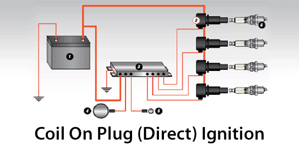
A COP system, as the name suggests, places the ignition coil directly on top of the spark plug. This eliminates the need for spark plug wires, reducing resistance and improving spark performance. Here's a breakdown of the key components:
* Ignition Coils: These are the heart of the system. Each coil is responsible for generating the high-voltage spark that ignites the air-fuel mixture in a single cylinder. They transform the low-voltage from the car's electrical system (typically 12V) into a very high voltage (20,000-40,000V or more) required to jump the gap in the spark plug. * Spark Plugs: These receive the high-voltage pulse from the ignition coil and create a spark within the combustion chamber. Different engines require different spark plugs with varying heat ranges and gap settings. * Engine Control Unit (ECU): The ECU is the brain of the operation. It determines when and for how long to fire each ignition coil based on inputs from various sensors like the crankshaft position sensor (CKP), camshaft position sensor (CMP), and others. * Crankshaft Position Sensor (CKP): This sensor monitors the position and speed of the crankshaft. The ECU uses this information to determine engine RPM and piston position. * Camshaft Position Sensor (CMP): This sensor monitors the position of the camshaft. The ECU uses this information to determine which cylinder is on its compression stroke and needs to be fired. * Wiring Harness: This connects all the components together, providing power and signal pathways. * Connectors: These provide secure and reliable connections between the components.Symbols and Conventions in a COP Diagram
Understanding the symbols used in the diagram is crucial for interpreting it correctly. While conventions can vary slightly between manufacturers, some common symbols include:
* Solid Lines: Represent wires carrying electrical current. * Dotted Lines: Often represent signal wires or communication lines. * Ground Symbol (usually three horizontal lines): Indicates a connection to the vehicle's chassis ground. * Battery Symbol: Represents the vehicle's battery, usually depicted as a series of alternating long and short lines. * Coil Symbol: A coiled wire symbol represents the ignition coil. * ECU Symbol: A rectangular box, often labeled "ECU" or "PCM" (Powertrain Control Module). * Sensor Symbols: Various symbols are used for sensors, often resembling their physical appearance or function. Consult the specific diagram's legend for detailed sensor symbol definitions. * Colors: Wires are often color-coded to help identify their function. A legend on the diagram will explain the color codes used. Example: red might be power, black might be ground.Remember to always refer to the diagram's specific legend for accurate symbol and color code interpretation. Ignoring this can lead to misdiagnosis and potentially damage the system.
How a COP System Works
The process is relatively straightforward, but understanding the sequence is key. Here's a simplified explanation:
1. Sensor Input: The CKP and CMP sensors send signals to the ECU, providing information about crankshaft and camshaft position. 2. ECU Calculation: The ECU processes these signals, along with inputs from other sensors, to determine the optimal ignition timing. 3. Coil Activation: The ECU sends a signal to the ignition coil, activating the coil's primary winding. 4. Magnetic Field Collapse: The ECU then cuts off the signal to the primary winding. This causes the magnetic field around the coil to collapse rapidly. 5. High-Voltage Generation: The collapsing magnetic field induces a very high voltage in the coil's secondary winding. 6. Spark Plug Ignition: This high-voltage pulse is sent to the spark plug, creating a spark that ignites the air-fuel mixture in the cylinder. 7. Repeat: This process repeats for each cylinder in the engine's firing order.The dwell time, which is the amount of time the primary winding is energized, is crucial for proper coil saturation. Insufficient dwell time can result in a weak spark, while excessive dwell time can overheat the coil.
Real-World Use: Basic Troubleshooting Tips
Armed with the diagram and an understanding of how the system works, you can start troubleshooting common COP issues:
* Misfires: Use an OBD-II scanner to identify the cylinder causing the misfire. Swap the ignition coil from the suspect cylinder with a known good coil. If the misfire moves to the new cylinder, the coil is likely the problem. If not, investigate the spark plug, wiring, or injector. * No Spark: Check for power and ground at the ignition coil connector using a multimeter. Verify the signal from the ECU using a logic probe or oscilloscope. A missing signal could indicate a problem with the ECU, wiring, or sensors. * Rough Idle: A rough idle can be caused by a weak spark, often due to a faulty ignition coil or spark plug. Inspect the spark plugs for wear or damage. * Poor Fuel Economy: A misfiring cylinder can lead to poor fuel economy. Diagnose and repair any misfires to improve fuel efficiency.When troubleshooting, always refer to the specific diagnostic procedures outlined in your vehicle's service manual. A multimeter, OBD-II scanner, and basic hand tools are essential for COP system diagnosis.
Safety Considerations
The COP ignition system deals with very high voltages. Take extreme caution when working around these components:
* Never work on the ignition system with the engine running. * Disconnect the negative battery cable before working on any electrical components. * Avoid touching the ignition coils or spark plug wires while the engine is running. * Use insulated tools when working on the ignition system. * Discharge the high voltage from the ignition coils before handling them. This can be done by carefully grounding the spark plug terminal of the coil after disconnecting it from the spark plug. * Be aware that capacitors in the system can hold a charge even after the battery is disconnected. Allow time for them to discharge, or follow specific discharging procedures outlined in the service manual.These precautions are critical. Working on the ignition system without taking proper safety measures can result in severe electric shock or even death.
With the insights gained from this article, and the detailed diagram available for download, you're well-equipped to understand, diagnose, and maintain your car's COP ignition system. Remember to consult your vehicle's specific service manual for detailed procedures and specifications.
We have the high-resolution COP ignition system diagram file available for download. This diagram will provide you with a detailed visual representation of the system, including wiring schematics, component locations, and sensor inputs. Having this diagram on hand is an invaluable resource for any DIY mechanic or car enthusiast.