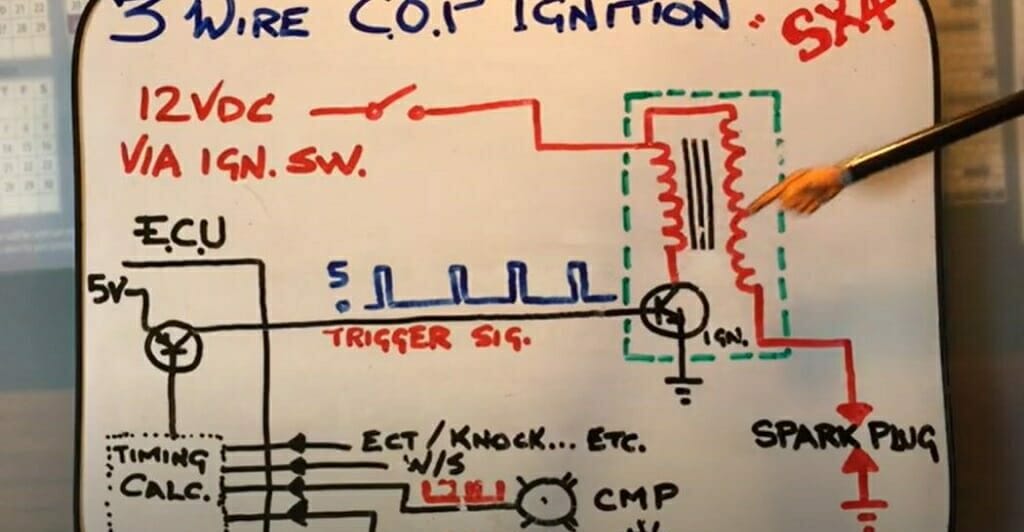
Coil Wiring 3 Wire Ignition Coil Diagram
Understanding your car's ignition system is crucial for maintaining performance, diagnosing issues, and even undertaking certain modifications. One of the core components of this system is the ignition coil, and knowing how it's wired – particularly a 3-wire coil – can be a lifesaver. This article will delve into the intricacies of a 3-wire ignition coil diagram, providing you with the knowledge to confidently tackle repairs, upgrades, or simply enhance your understanding of automotive electrical systems.
Purpose of a 3-Wire Ignition Coil Diagram
A 3-wire ignition coil diagram serves several essential purposes:
- Troubleshooting: When your engine misfires, runs poorly, or refuses to start, the ignition coil is a prime suspect. The diagram helps you trace the wiring, check for continuity, and verify proper voltage at each terminal.
- Repairs and Replacements: If you need to replace a faulty coil or repair damaged wiring, the diagram ensures you connect everything correctly. Incorrect wiring can damage the coil, the engine control unit (ECU), or other components.
- Performance Upgrades: Modders often upgrade ignition coils for improved spark energy, especially in tuned or high-performance engines. A diagram is essential for proper installation and ensuring compatibility.
- Learning and Education: For aspiring mechanics or those simply curious about automotive technology, understanding the diagram provides a deeper insight into how the ignition system functions.
Key Specs and Main Parts of a 3-Wire Ignition System
Before diving into the diagram, let's define the key components and specifications:
- Ignition Coil: The heart of the system, the coil transforms low-voltage power from the battery into the high-voltage needed to create a spark at the spark plug. Modern coils are often individual units mounted directly on the spark plug (coil-on-plug or COP) or are part of a coil pack serving multiple cylinders.
- Primary Winding: This is the lower-voltage side of the coil. In a 3-wire setup, two of the wires connect to this winding.
- Secondary Winding: This is the high-voltage side, producing the spark. It's internally connected within the coil.
- ECU (Engine Control Unit): The "brain" of the engine, the ECU controls the timing and duration of the ignition spark.
- Battery Voltage: Typically 12V DC, supplied from the car's battery.
- Spark Plug: The device that ignites the air-fuel mixture in the cylinder.
- Firing Order: The sequence in which the spark plugs fire, determined by the engine's design.
For a 3-wire ignition coil specifically:
- Power (12V): Supplies the coil with the necessary voltage to charge the primary winding.
- Ground: Provides a return path for the current flowing through the primary winding. It may also be the coil body.
- Trigger Signal (from ECU): This signal tells the coil when to discharge its stored energy and create a spark. The ECU rapidly switches this signal on and off to control spark timing. This is often a pulse-width modulated (PWM) signal.
Understanding Symbols in a 3-Wire Ignition Coil Diagram
Electrical diagrams use standardized symbols to represent components and connections. Understanding these symbols is crucial for interpreting the diagram correctly.
- Lines: Solid lines represent wires. Dashed lines may represent shielding or connections to other systems. The thickness of the lines doesn't typically represent wire gauge, unless specifically noted.
- Colors: Wire colors are extremely important for identifying the correct wires. Common colors include red (power), black (ground), and various other colors for signal wires. The diagram legend should specify the color codes.
- Coil Symbol: Usually represented by a series of curved lines resembling a spring or a tightly wound wire. Sometimes, the primary and secondary windings are shown separately.
- Ground Symbol: Typically depicted as a series of horizontal lines decreasing in size, representing a connection to the vehicle's chassis or ground.
- Battery Symbol: Usually shown as a series of long and short parallel lines.
- ECU Symbol: Often represented as a box or rectangle with labeled input and output terminals.
Important Note: Always refer to the specific diagram for your vehicle model, as symbols and color codes can vary between manufacturers and even different models from the same manufacturer.
How a 3-Wire Ignition Coil Works
The 3-wire ignition coil operates on the principle of electromagnetic induction. Here's a breakdown of the process:
- Charging the Primary Winding: When the ECU "turns on" the trigger signal (completes the circuit between the ECU and ground), current flows from the battery, through the 12V power wire, into the primary winding of the coil, and back to ground via the ground wire. This current flow creates a magnetic field around the primary winding.
- Building Magnetic Field: This current is allowed to flow for a pre-determined length of time (dwell time). The longer it flows the stronger the magnetic field builds up.
- Discharging the Coil: When the ECU wants to fire the spark plug, it "turns off" the trigger signal (opens the circuit between the ECU and ground). This rapidly collapses the magnetic field in the primary winding.
- Inducing High Voltage: The collapsing magnetic field induces a high-voltage current in the secondary winding. Due to the high turns ratio between the primary and secondary windings (typically hundreds or thousands to one), the voltage is amplified significantly (tens of thousands of volts).
- Spark Generation: This high-voltage surge is then directed to the spark plug, creating a spark across the spark plug gap, igniting the air-fuel mixture in the cylinder.
Real-World Use: Basic Troubleshooting
Here are some basic troubleshooting tips using the 3-wire ignition coil diagram:
- No Spark:
- Check for 12V at the power wire terminal using a multimeter. If no voltage, check the fuse and wiring.
- Verify the ground connection is solid. A poor ground can prevent the coil from charging.
- Use an oscilloscope or logic probe to check for a trigger signal from the ECU while cranking the engine. If there's no signal, the ECU or its wiring may be faulty.
- Weak Spark:
- Could indicate a failing coil. Try replacing the coil with a known good one.
- Check the spark plug gap. An incorrect gap can lead to a weak spark.
- Look for corrosion or damage in the wiring, which can reduce voltage to the coil.
- Misfires:
- Can be caused by a faulty coil, spark plug, or wiring. Use the diagram to check continuity and voltage at each component.
- Consider checking the coil resistance. A significant deviation from the specified resistance indicates a problem with the coil windings.
Important: Always disconnect the battery's negative terminal before working on the electrical system to prevent shorts and potential damage.
Safety Precautions
Working with ignition systems involves high voltages, so safety is paramount:
- High Voltage: The secondary side of the coil produces extremely high voltage that can be lethal. Never touch the spark plug wire or coil terminals while the engine is running or being cranked.
- Fuel Vapors: Be careful around fuel vapors when testing for spark. A stray spark can ignite the vapors and cause a fire or explosion. Ensure adequate ventilation.
- Disconnect Battery: As mentioned earlier, always disconnect the battery's negative terminal before working on the electrical system to prevent accidental shorts.
The ECU is a sensitive electronic device. Avoid static electricity and handle it with care. Always consult the vehicle's service manual for specific safety precautions related to the ignition system.
We have a sample 3-wire ignition coil diagram file available for download. It provides a visual representation of the connections and wire colors, helping you better understand the concepts discussed in this article. Remember to always compare the available diagram with the wiring of your specific vehicle to make sure the information applies.