Color Code Car Stereo Wiring Diagram
Understanding a car stereo wiring diagram is absolutely essential whether you're upgrading your audio system, troubleshooting a faulty connection, or simply learning the ins and outs of your vehicle's electrical architecture. It's the roadmap that guides you through the intricate web of wires connecting your head unit (the main radio receiver) to speakers, power sources, and other components.
Purpose of a Car Stereo Wiring Diagram
A car stereo wiring diagram serves several critical purposes. Primarily, it enables you to:
- Correctly Install a New Head Unit: Aftermarket head units often have different wiring configurations than the factory-installed one. The diagram ensures you connect each wire to the correct corresponding wire in your car's harness.
- Troubleshoot Audio Problems: Identify broken or misconnected wires, blown fuses, or grounding issues that can cause sound distortion, intermittent power, or complete system failure.
- Install Amplifiers and Subwoofers: Connect these components properly to the head unit's RCA outputs (pre-amp outputs) and the car's power and ground.
- Repair Damaged Wiring: Repair damaged wires due to wear, tear, or corrosion to restore sound quality and functionality.
- Learn and Understand: Gain a better understanding of automotive electrical systems and how the car stereo integrates within it.
Key Specs and Main Parts
Before diving into the diagram itself, it's important to know the key components and specifications involved:
- Head Unit (Radio/Receiver): The central hub of the system, providing the user interface, AM/FM tuner, CD player (in some models), Bluetooth connectivity, and audio processing.
- Speakers: Responsible for converting electrical signals into audible sound. Typically, you'll have front (left and right) and rear (left and right) speakers. Some vehicles also include tweeters (high-frequency speakers) and subwoofers (low-frequency speakers).
- Amplifier (Optional): Boosts the audio signal from the head unit to drive the speakers with more power, resulting in louder and cleaner sound. Often required for subwoofers.
- Wiring Harness: A bundle of wires that connects the head unit to the car's electrical system. Aftermarket head units usually require an adapter harness to interface with the vehicle's existing wiring.
- Ground Wire: Provides a return path for the electrical current and is essential for proper operation. Often connected to the car's chassis.
- Power Wire (12V Constant): Supplies continuous power to the head unit for memory functions, even when the ignition is off.
- Accessory Wire (12V Switched): Provides power to the head unit only when the ignition is turned on.
- Remote Turn-On Wire (Amplifier): Signals the amplifier to turn on when the head unit is powered on.
- RCA Cables: Used to transmit pre-amplified audio signals from the head unit to an amplifier.
- Speaker Wire: Conducts the amplified audio signal from the amplifier to the speakers. Typically 16 or 18 gauge.
Symbols in a Car Stereo Wiring Diagram
Understanding the symbols used in a car stereo wiring diagram is crucial for interpreting the information correctly. Here's a breakdown of common symbols:
- Lines: Represent wires. The thickness of the line doesn't necessarily indicate wire gauge, but it's helpful to note if there are distinct differences in thickness within a single diagram, as thicker lines often represent power or ground wires.
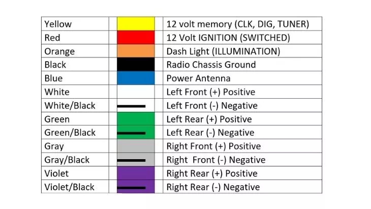
- Colors: Each wire is assigned a specific color code. Common colors include Red (12V Constant), Yellow (12V Switched/Accessory), Black (Ground), White (Front Left +), White/Black Stripe (Front Left -), Gray (Front Right +), Gray/Black Stripe (Front Right -), Green (Rear Left +), Green/Black Stripe (Rear Left -), Purple (Rear Right +), Purple/Black Stripe (Rear Right -), and Blue (Remote Turn-On). However, always verify the color coding with your specific vehicle's wiring diagram, as manufacturers can vary.
- Circles or Dots: Indicate connection points or splices where wires are joined together.
- Rectangles or Squares: Represent components like the head unit, amplifier, or speakers. Labels within these shapes identify the specific component.
- Ground Symbol: Usually a series of horizontal lines decreasing in size, indicating a connection to the vehicle's chassis ground.
- Fuse Symbol: Represented by a jagged line within a rectangle or cylinder, indicating the location of a fuse.
How It Works: Following the Circuit
A car stereo wiring diagram depicts the electrical circuit that powers and operates the audio system. The diagram shows how power flows from the car's battery, through fuses (for protection), to the head unit. The head unit then distributes power and audio signals to the speakers and amplifier (if present). The ground wire completes the circuit, providing a return path for the current back to the battery.
Tracing a circuit involves following the lines (wires) from the power source, through the various components, and back to ground. By understanding the flow of electricity, you can identify potential problems such as breaks in the circuit (open circuit), short circuits (where electricity flows directly to ground bypassing the intended component), or high resistance connections (which can cause voltage drop and poor performance).
Real-World Use: Basic Troubleshooting Tips
Here are some basic troubleshooting tips when using a car stereo wiring diagram:
- No Power to Head Unit: Check the 12V constant and 12V switched/accessory wires. Use a multimeter to verify voltage at these points. Also, check the corresponding fuses in the car's fuse box.
- No Sound from Speakers: Verify the speaker wire connections at both the head unit and the speakers. Check the speaker wire continuity using a multimeter. If using an amplifier, ensure it is receiving power and a remote turn-on signal.
- Distorted Sound: Check for loose speaker wire connections or damaged speakers. A blown speaker will often produce distorted or no sound.
- Intermittent Sound: Check for loose connections, especially at the wiring harness. Also check the ground connection to ensure it's secure and free of corrosion.
- Blown Fuses: If a fuse repeatedly blows, it indicates a short circuit. Trace the wiring to identify the cause of the short. Do not simply replace the fuse with a higher amperage fuse, as this can cause a fire.
Safety Precautions
Working with automotive electrical systems can be dangerous if proper precautions are not taken:
- Disconnect the Battery: Always disconnect the negative terminal of the car battery before working on the electrical system. This prevents accidental shorts and potential electrical shocks.
- Use Proper Tools: Use insulated tools designed for electrical work to prevent shorts and shocks.
- Avoid Working with Live Wires: Never work on wiring while the ignition is on or the battery is connected unless absolutely necessary for testing, and then proceed with extreme caution.
- Identify Risky Components: Be particularly careful when working with the airbag system. Incorrect wiring can cause the airbag to deploy unexpectedly. Consult a professional if you are unsure about working around airbags.
- Consult a Professional: If you are not comfortable working on your car's electrical system, consult a qualified automotive electrician.
Remember, a wiring diagram is just a guide. Always double-check wire colors and connections with your vehicle's specific documentation. We have a sample car stereo wiring diagram file available for download to help you further understand and apply these concepts. This file provides a visual representation that complements this article, helping you visualize and practically apply the knowledge you've gained. With careful planning and attention to detail, you can successfully install, troubleshoot, and repair your car stereo system.
[Download link would go here, e.g., Download Sample Wiring Diagram (PDF) ]