
Color Code Metra Wiring Harness Diagram
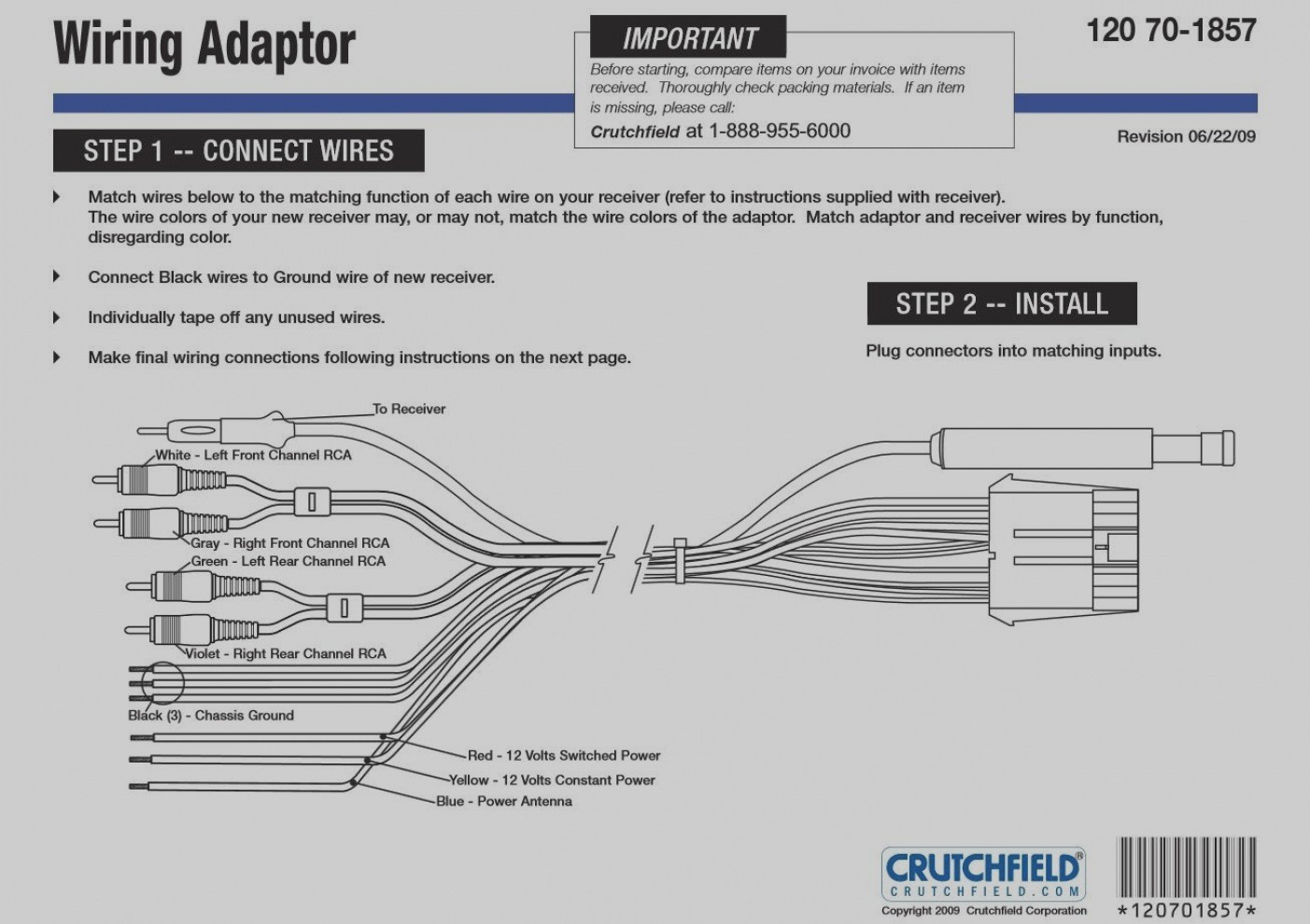
Alright, let's dive into the world of Metra wiring harnesses. If you're tinkering with your car's audio system, replacing a head unit, or even installing aftermarket accessories, understanding the Metra wiring harness diagram is absolutely crucial. Consider this your comprehensive guide to navigating these often-intimidating schematics.
Purpose: Why You Need This Diagram
So, why bother with a Metra wiring harness diagram? Simple: it's your roadmap to a successful and safe installation or repair. These diagrams serve several critical purposes:
- Simplified Head Unit Installation: Aftermarket head units rarely have the same connector as your factory radio. A Metra harness acts as an adapter, bridging the gap. The diagram tells you precisely which wire from the Metra harness connects to which wire on the new head unit, preventing you from guessing and potentially damaging your car's electrical system.
- Accurate Wiring for Accessories: Installing amplifiers, speakers, or other accessories requires tapping into existing wiring. The diagram shows you where to safely and correctly connect these components.
- Troubleshooting Electrical Issues: Got a speaker that's not working? A blown fuse? The diagram helps you trace the wiring path to identify the source of the problem.
- Educational Tool: Even if you're not actively working on your car, studying the diagram provides valuable insight into how your car's audio system is wired, fostering a deeper understanding of automotive electrical systems.
Key Specs and Main Parts of a Metra Wiring Harness
A Metra wiring harness consists of two main parts:
- Vehicle-Specific Connector: This connector plugs directly into your car's factory radio harness. It's designed to fit perfectly and securely, ensuring a solid connection.
- Aftermarket Radio Connector: This connector is designed to plug into the back of your aftermarket radio. It typically follows a standardized wiring scheme.
Key specifications to note when selecting a Metra harness:
- Vehicle Make, Model, and Year: Metra harnesses are vehicle-specific. Ensure you choose the correct harness for your car to guarantee compatibility. Using the wrong harness can lead to damage.
- Radio Type (Amplified/Non-Amplified): Some vehicles have factory amplifiers. You'll need a different type of Metra harness for these systems to properly integrate with the amplifier. Using the wrong type can cause distortion or no sound at all.
- Steering Wheel Control Compatibility: If you want to retain your steering wheel controls, you'll need a Metra harness and possibly an additional adapter specifically designed for this purpose.
Symbols: Decoding the Wiring Diagram
Understanding the symbols on a Metra wiring diagram is essential. Here's a breakdown of common elements:
- Lines: Solid lines represent wires. The thickness of the line doesn't usually indicate wire gauge.
- Colors: Each wire is assigned a specific color, such as red, black, yellow, blue, etc. The color code is extremely important. Match the wire colors from the Metra harness to the corresponding wires on the aftermarket head unit.
- Abbreviations: Common abbreviations include:
- GND: Ground
- BAT: Battery (constant 12V+)
- ACC: Accessory (switched 12V+)
- REM: Remote Turn-On (for amplifiers)
- FL, FR, RL, RR: Front Left, Front Right, Rear Left, Rear Right (speakers)
- Connectors: Represented as squares or rectangles, showing the points where wires connect.
- Fuses: A zig-zag line within a small rectangle usually indicates a fuse.
- Ground Symbols: Often depicted as a series of decreasing horizontal lines, signifying a connection to the vehicle's chassis (ground).
The diagram will typically include a color chart, mapping each wire color to its function. Pay close attention to this chart!
How It Works: Translating the Diagram to Reality
The diagram acts as a key, connecting the wires from your car's factory harness to the appropriate wires on your aftermarket radio. The process typically involves these steps:
- Identify the Wires: Using the Metra diagram and the wiring diagram for your aftermarket head unit, identify the function of each wire (e.g., power, ground, speaker wires, remote turn-on).
- Connect the Wires: Connect the corresponding wires from the Metra harness to the wires from your aftermarket head unit. You can use butt connectors, solder and heat shrink tubing, or crimp connectors. Solder and heat shrink tubing provide the most reliable and durable connection.
- Plug in the Harness: Once all the connections are made, plug the vehicle-specific connector into your car's factory radio harness and the aftermarket radio connector into the back of your new head unit.
- Test: Before fully reassembling the dashboard, test the radio to ensure everything is working correctly.
Real-World Use: Basic Troubleshooting Tips
Even with a diagram, issues can arise. Here are some common troubleshooting tips:
- No Power: Double-check the ground connection. Ensure the battery wire (usually yellow) is receiving constant 12V+ and the accessory wire (usually red) is receiving 12V+ when the ignition is turned on. Also, check the fuses in both the car and the head unit.
- No Sound: Verify that the speaker wires are connected correctly (positive to positive, negative to negative). Check the fader and balance settings on the head unit. Ensure that the amplifier turn-on wire (if applicable) is connected correctly.
- Steering Wheel Controls Not Working: If you're using a steering wheel control adapter, ensure it's programmed correctly. Verify that the adapter is connected to the correct wires on the Metra harness and the head unit.
- Distortion: Check for loose connections or shorts in the speaker wiring. Ensure that the impedance (ohms) of your speakers matches the head unit or amplifier's specifications.
Safety: Handle with Care
Working with automotive electrical systems can be dangerous. Here are some safety precautions:
- Disconnect the Battery: Always disconnect the negative battery terminal before working on any electrical components to prevent short circuits and potential electrocution.
- Use Proper Tools: Use insulated tools designed for automotive electrical work.
- Avoid Water: Never work on electrical systems in wet or damp conditions.
- Be Mindful of the Airbag System: Some vehicles have airbags located near the radio. Be extremely careful not to damage any airbag wiring or components. A deployed airbag can cause serious injury.
- Don't Overload Circuits: Avoid tapping into existing circuits to power too many accessories. This can overload the circuit and cause a fire. Use a dedicated circuit with a fuse for each accessory.
- Be especially careful with the airbag system - improper handling can lead to accidental deployment!
By understanding the Metra wiring harness diagram and following these tips, you can confidently tackle your car audio projects. We have a downloadable Metra wiring harness diagram available for common vehicles. This resource will provide you with a visual aid to help you identify the wires in your vehicle's factory wiring harness. Contact us, and we'll gladly provide the file to you.