Color Code Radio Wiring Nissan Stereo Wiring Diagram
Understanding the color code radio wiring diagram for your Nissan stereo is crucial for various reasons, from simple repairs to complex aftermarket upgrades. Whether you're replacing a faulty head unit, installing a new amplifier, or just trying to understand your car's audio system, this diagram serves as a vital roadmap. This guide will provide a comprehensive breakdown of a typical Nissan stereo wiring diagram, empowering you to confidently tackle your next car audio project.
Purpose of the Nissan Stereo Wiring Diagram
The primary purpose of a stereo wiring diagram is to provide a visual representation of all the electrical connections within the audio system. It details the functions of each wire, their color codes, and their destinations. This information is indispensable for:
- Troubleshooting: Identifying faulty wiring or incorrect connections that may be causing audio problems.
- Installation: Connecting aftermarket stereos, amplifiers, speakers, or other audio components correctly.
- Repair: Fixing damaged or corroded wires.
- Modification: Customizing your audio system by adding features or upgrading components.
- Understanding: Gain a deeper understanding of how your car's audio system works.
Key Specs and Main Parts
A typical Nissan stereo wiring diagram includes various components, each with its specific function. Understanding these components is key to interpreting the diagram effectively.
Power Supply
The diagram will clearly indicate the power source, typically the car's battery. Key wires include:
- +12V Constant (Battery): Provides continuous power to the head unit to retain settings and memory. This is often a yellow wire.
- +12V Switched (Ignition): Supplies power only when the ignition is turned on. This is typically a red wire. This wire tells the stereo when to turn on and off.
- Ground: Provides the return path for the electrical current. Usually a black wire and connected to the car's chassis. A proper ground is absolutely crucial for proper stereo function.
Speaker Wires
These wires connect the head unit to the speakers. Each speaker (front left, front right, rear left, rear right) will have two wires: a positive (+) and a negative (-) wire. Speaker wires are frequently twisted pairs of similar but distinct colors (e.g., white/black stripe and solid white). Identifying these correctly is critical to maintain proper polarity.
Remote Turn-On Wire (Amplifier Turn-On)
A blue wire, sometimes with a white stripe, is used to signal aftermarket amplifiers to turn on when the head unit is powered up. This wire provides a low-current +12V signal to the amplifier. It's essential for preventing a constant drain on your car's battery.
Antenna Wire
This wire connects the head unit to the car's antenna. It may be a coaxial cable or a standard wire. On some Nissans, this wire may also need a 12v power supply from the head unit, also in the headunit wiring loom. This is usually a blue wire.
Other Wires
Depending on the complexity of the system, the diagram may also include wires for:
- Illumination: Dims the head unit's display when the headlights are turned on.
- Steering Wheel Controls: Connects the head unit to the car's steering wheel controls. These usually require a separate adapter.
- Navigation Systems: Wires for GPS antenna, vehicle speed sensor, reverse signal, etc.
Symbols and Color Codes
Understanding the symbols and color codes used in the diagram is paramount. Standard symbols represent electrical components like resistors, capacitors, and fuses. Lines represent wires, and their colors indicate the function of each wire.
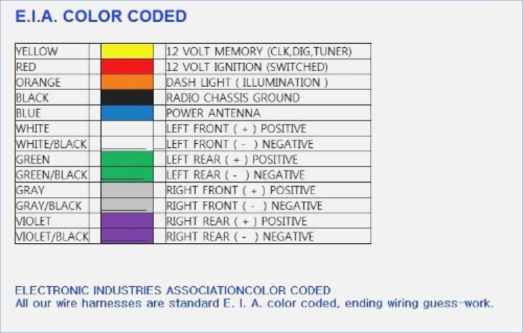
While specific colors may vary slightly between Nissan models and years, the following are common color codes:
- Yellow: +12V Constant (Battery)
- Red: +12V Switched (Ignition)
- Black: Ground
- White: Front Left Speaker (+)
- White/Black Stripe: Front Left Speaker (-)
- Gray: Front Right Speaker (+)
- Gray/Black Stripe: Front Right Speaker (-)
- Green: Rear Left Speaker (+)
- Green/Black Stripe: Rear Left Speaker (-)
- Purple: Rear Right Speaker (+)
- Purple/Black Stripe: Rear Right Speaker (-)
- Blue: Remote Turn-On (Amplifier) or Antenna Power
- Orange: Illumination
The diagram will typically use a legend or key to explain any other symbols or specific color codes used. Pay close attention to any notes provided on the diagram itself.
How It Works: Following the Signal Path
The diagram allows you to trace the signal path from the power source, through the head unit, and to the speakers. When the ignition is turned on, the +12V switched wire provides power to the head unit. The head unit then processes audio signals from various sources (radio, CD, Bluetooth) and amplifies them. These amplified signals are then sent to the speakers via the speaker wires.
Understanding this basic flow is essential for troubleshooting. For example, if you have no sound from one speaker, you can trace the speaker wires back to the head unit to check for loose connections or damaged wires. If the head unit isn't turning on at all, you can focus on the power supply wires (yellow, red, and black).
Real-World Use: Basic Troubleshooting Tips
Here are some practical troubleshooting tips using the wiring diagram:
- No Power to Head Unit: Check the +12V constant (yellow) and +12V switched (red) wires with a multimeter to ensure they are receiving power. Also, verify the ground connection is secure. Inspect the fuses related to the stereo system.
- No Sound from a Speaker: Check the speaker wires for continuity (using a multimeter) and proper connection at both the head unit and the speaker. Ensure the speaker itself is functional.
- Constant Battery Drain: If your car battery is constantly draining, the remote turn-on wire may be improperly connected, causing the amplifier to remain on even when the car is off.
- Distorted Sound: Check for shorts or loose connections in the speaker wires. Incorrect speaker polarity can also cause sound cancellation and distortion.
When troubleshooting, always disconnect the negative terminal of the battery to prevent electrical shocks or damage to the car's electrical system.
Safety Considerations
Working with car electrical systems can be dangerous if proper precautions are not taken. Here are some critical safety tips:
- Disconnect the Battery: Always disconnect the negative terminal of the car battery before working on any electrical components. This prevents short circuits and electrical shocks.
- Use a Multimeter: A multimeter is an essential tool for testing voltage, continuity, and resistance. Learn how to use it properly.
- Avoid Cutting Wires Unnecessarily: Only cut wires when absolutely necessary. Use wire strippers and connectors to make clean and secure connections.
- Proper Grounding: Ensure all ground connections are secure and connected to a clean, unpainted metal surface.
- Fuse Protection: Always use fuses with the correct amperage rating to protect the electrical circuits.
- Airbags: Be extremely careful when working near airbags. Disconnecting the battery is crucial, and it's often best to consult a professional if you're unsure.
Working with airbags incorrectly can result in serious injury.
The +12V constant (Battery) and +12V switched (Ignition) wires are "hot" and can easily create a short if contacted to ground.
By understanding the color code radio wiring diagram for your Nissan stereo and following these safety precautions, you can confidently troubleshoot and upgrade your car's audio system. Remember to consult your car's service manual or a trusted mechanic if you encounter any difficulties.
We have a sample Nissan Stereo Wiring Diagram file available for download. This diagram can be a helpful visual aid as you're working on your project. It covers a range of common Nissan models and provides clear labeling for all wires and connections. Understanding the diagram is half the battle.
Remember to always double-check the wiring configuration for your specific Nissan model year, as slight variations may exist. Good luck, and happy wiring!