Color Code Toyota Camry Radio Wiring Diagram
Understanding the Toyota Camry radio wiring diagram is crucial for any car enthusiast, DIY mechanic, or modder who wants to upgrade their sound system, troubleshoot audio issues, or perform custom modifications. It's like having a roadmap to the electrical heart of your Camry's audio system. Instead of blindly guessing, you can use this diagram to confidently navigate the complex network of wires and connections. We'll explore the purpose of these diagrams, decipher their symbols, and provide practical tips for using them safely and effectively.
Why Bother with a Radio Wiring Diagram?
Radio wiring diagrams serve several essential purposes:
- Troubleshooting: Diagnosing issues like a dead radio, speaker malfunctions, or intermittent signal problems becomes significantly easier with a wiring diagram. You can trace circuits, identify faulty components, and pinpoint the source of the problem.
- Upgrades and Modifications: Want to install a new head unit, amplifier, or subwoofer? The wiring diagram shows you exactly where to tap into the existing system, ensuring proper connections and avoiding damage to your vehicle's electrical components.
- Repairs: If a wire is damaged or a connector is broken, the diagram helps you identify the correct replacement and ensures that it's wired correctly.
- Learning and Understanding: Even if you don't have an immediate need, studying the wiring diagram provides valuable insight into how your car's audio system is designed and how its components interact.
Key Specs and Main Parts Illustrated
A typical Toyota Camry radio wiring diagram illustrates the following key specs and components:
- Power Supply: This section shows the wires that provide power to the radio, typically a constant 12V+ (usually a thick red or yellow wire) for memory retention, a switched 12V+ (often red or pink) that turns on with the ignition, and a ground connection (usually black or brown). Correctly identifying these wires is paramount to prevent short circuits and damage to your radio.
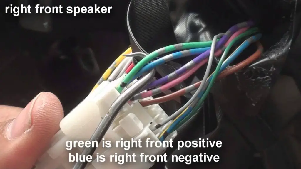
- Speaker Outputs: These are the wires that connect the radio to the speakers. They are typically identified by color-coding and often come in pairs (positive and negative) for each speaker. Common colors include white, gray, green, and purple, often with a stripe.
- Antenna Connection: The diagram shows the location of the antenna wire, which is usually a coaxial cable with a specific connector.
- Illumination Wire: This wire dims the radio display when the headlights are turned on. It is usually orange or white with a blue stripe.
- Remote Turn-On: This wire provides a 12V+ signal to turn on external amplifiers when the radio is powered on. Usually a blue or blue/white wire.
- Steering Wheel Control Wires: Many modern Camry models have steering wheel controls for the radio. The diagram will show the wires that connect these controls to the radio. These usually require an adapter for aftermarket radio headunits.
- Factory Amplifier (if equipped): If your Camry has a factory amplifier, the diagram will show its location and wiring connections. These connections are often more complex than those in models without an amplifier.
Deciphering the Diagram: Symbols, Lines, and Colors
Understanding the symbols, lines, and colors used in a radio wiring diagram is essential for accurate interpretation:
- Lines: Solid lines represent wires, and dashed lines may represent shielded cables or connections to ground.
- Colors: Each wire is identified by a specific color code, usually abbreviated (e.g., "RED" for red, "BLU" for blue, "BLK" for black, "GRN" for green, "YEL" for yellow, "WHT" for white). It's crucial to adhere to these colors when making connections. A color code like "GRN/WHT" means a green wire with a white stripe.
- Symbols: Common symbols include:
- Ground: Represented by a downward-pointing triangle or a series of horizontal lines.
- Resistor: A zig-zag line.
- Capacitor: Two parallel lines.
- Diode: A triangle pointing to a vertical line.
- Fuse: A small box with a wavy line inside.
- Connector: A circle or square where multiple wires connect.
- Abbreviations: Diagrams use abbreviations to save space. Learn common electrical abbreviations like "ACC" (accessory), "GND" (ground), "IGN" (ignition), "SPK" (speaker), "AMP" (amplifier), and "REM" (remote).
How It Works: Tracing the Circuits
The wiring diagram provides a visual representation of the electrical circuits in your Camry's audio system. To understand how it works, start by identifying the power supply. Trace the 12V+ constant and switched power wires from the fuse box to the radio. Then, follow the ground wire to its grounding point on the vehicle's chassis. Next, identify the speaker outputs and trace them to the corresponding speakers. This process will help you understand the flow of electricity through the system and identify potential points of failure.
For example, if you're experiencing a problem with the left front speaker, you can use the diagram to trace the wiring from the radio to the speaker. This will allow you to check for loose connections, damaged wires, or a faulty speaker. Similarly, if the radio isn't turning on, you can check the power supply wires and the fuse associated with the radio circuit.
Real-World Use: Basic Troubleshooting Tips
Here are some basic troubleshooting tips using the radio wiring diagram:
- No Power to Radio:
- Check the fuses related to the radio circuit. Replace any blown fuses with the correct amperage rating.
- Use a multimeter to check for voltage at the constant and switched power wires at the radio connector. If there's no voltage, trace the wires back to the fuse box or ignition switch.
- Ensure the ground wire is securely connected to the vehicle's chassis.
- Speaker Not Working:
- Check the speaker wires for loose connections or damage.
- Use a multimeter to check the speaker's impedance. A very low or very high impedance indicates a faulty speaker.
- Swap the speaker with a known working speaker to rule out a speaker issue.
- Distorted Sound:
- Check the speaker wires for shorts to ground.
- Inspect the speakers for damage.
- Ensure the amplifier (if equipped) is properly configured and not overloaded.
Safety First: Identifying Risky Components
Working with automotive electrical systems can be dangerous. Always disconnect the negative terminal of the battery before working on any electrical components. Pay particular attention to the following:
- Airbag Circuits: Some wiring may be routed near airbag sensors or modules. Avoid disturbing these circuits, as accidental deployment of an airbag can cause serious injury. If you need to work near airbag components, consult a qualified technician.
- High-Current Wires: The power supply wires to the radio carry significant current. Shorting these wires can cause a fire or damage to your vehicle's electrical system.
- Factory Amplifiers: If your Camry has a factory amplifier, it may operate at higher voltages. Exercise caution when working with amplifier wiring.
Before beginning any work, take the time to carefully review the wiring diagram and identify the components you'll be working with. Use proper tools and techniques to avoid damaging wires or connectors. If you're unsure about any aspect of the process, consult a qualified technician.
This guide is intended to provide a basic understanding of Toyota Camry radio wiring diagrams. Always refer to the specific wiring diagram for your vehicle's model year and trim level.
We have compiled a detailed Toyota Camry radio wiring diagram file. You can download it to assist in your projects, repairs, and customizations. Click below to access the document.
Download the Toyota Camry Radio Wiring Diagram