Color Coded Wiring Fuel Pump Wires Color Codes
Understanding your vehicle's electrical system, particularly the fuel pump wiring, is crucial for effective diagnostics, repairs, and modifications. This article serves as a comprehensive guide to interpreting fuel pump wiring diagrams and color codes, empowering you to confidently tackle related projects. We'll cover the purpose of these diagrams, key components, how the system functions, real-world applications, and essential safety precautions.
Purpose of Fuel Pump Wiring Diagrams and Color Codes
Fuel pump wiring diagrams are essentially roadmaps of the electrical circuits controlling your fuel pump. They provide a visual representation of the wiring layout, showing the connections between various components and their corresponding wire colors. Understanding these diagrams is vital for several reasons:
- Troubleshooting: When your fuel pump malfunctions, the diagram helps you trace the circuit to identify the source of the problem (e.g., a broken wire, a faulty relay, or a damaged pump).
- Repairs: Once you've identified the issue, the diagram guides you in making the necessary repairs, ensuring you reconnect wires correctly and avoid further damage.
- Modifications: If you're upgrading your fuel pump or adding aftermarket components, the diagram helps you integrate the new equipment into the existing electrical system safely and effectively.
- Learning: Even if you don't have an immediate problem, studying the diagram can deepen your understanding of automotive electrical systems and improve your overall diagnostic skills.
Key Specs and Main Parts of a Fuel Pump Circuit
A typical fuel pump circuit includes the following key components:
- Fuel Pump: The heart of the system, responsible for drawing fuel from the tank and delivering it to the engine at the correct pressure. Its resistance (measured in ohms) is a crucial diagnostic parameter.
- Fuel Pump Relay: An electrically operated switch that controls the flow of power to the fuel pump. This relay is often controlled by the Engine Control Unit (ECU).
- ECU (Engine Control Unit): The "brain" of the engine, responsible for managing various engine functions, including fuel delivery. It sends a signal to the fuel pump relay to activate the pump.
- Inertia Switch (Fuel Cut-off Switch): A safety device that cuts power to the fuel pump in the event of a collision, preventing fuel leakage and potential fires.
- Wiring Harness: A bundle of wires that connects all the components in the circuit.
- Fuses: Protective devices that prevent damage to the circuit in case of a short circuit or overload.
- Ground Connections: Essential for completing the electrical circuit. A poor ground can cause a variety of problems.
Understanding Wiring Diagram Symbols
Wiring diagrams use a standardized set of symbols to represent different components and connections. Familiarizing yourself with these symbols is essential for interpreting the diagram accurately.
- Lines: Represent wires. Solid lines typically indicate a direct connection, while dashed lines may indicate a shielded wire or a connection through a connector.
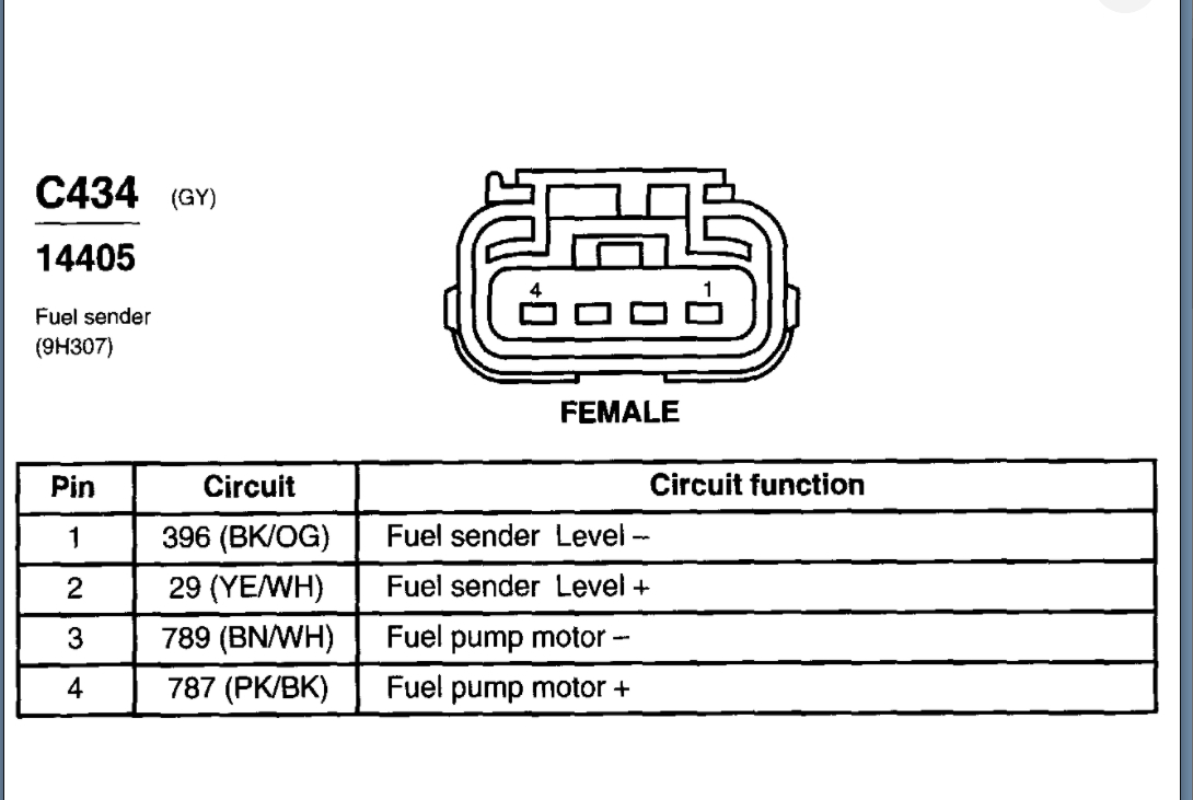
- Wire Colors: Each wire is typically identified by a color code (e.g., BLK for Black, RED for Red, GRN for Green). Some wires may have a primary color and a stripe of another color (e.g., GRN/WHT for Green with a White stripe). Understanding these color codes is critical for identifying the correct wires.
- Symbols for Components:
- Relay: Often represented by a rectangle with a coil symbol inside and a switch symbol adjacent.
- Fuse: Represented by a squiggly line inside a rectangle.
- Ground: Represented by a series of horizontal lines decreasing in size.
- Connectors: Represented by interlocking symbols.
- Fuel Pump: Typically represented by a circle with a pump symbol inside.
- Numbers and Letters: These may indicate wire gauge (thickness), circuit number, or connector pin number.
Important Note: While there are general conventions, wiring diagrams can vary slightly depending on the vehicle manufacturer and model year. Always refer to the specific diagram for your vehicle.
How the Fuel Pump Circuit Works
The fuel pump circuit works as follows:
- When you turn the ignition key to the "ON" position, the ECU sends a signal to the fuel pump relay.
- The fuel pump relay closes, allowing power to flow from the battery (via a fuse) to the fuel pump.
- The fuel pump starts running, drawing fuel from the tank and delivering it to the fuel rail at the engine.
- The ECU continuously monitors engine parameters and adjusts the fuel pump voltage or pulse width modulation (PWM) to regulate fuel pressure and flow. PWM is a method used to control the fuel pumps voltage and can often be checked with an oscilloscope.
- If the inertia switch is triggered (e.g., in a collision), it interrupts the power supply to the fuel pump, shutting it off.
Real-World Use: Basic Troubleshooting Tips
Here are some basic troubleshooting tips using the wiring diagram:
- No Fuel Pump Operation: If the fuel pump isn't running, start by checking the fuel pump fuse. If the fuse is blown, replace it and see if it blows again. If it continues to blow, there's likely a short circuit in the wiring. Use the diagram to trace the circuit and identify potential areas of damage.
- Intermittent Fuel Pump Operation: This could be caused by a faulty fuel pump relay, a loose connection, or a failing fuel pump. Use the diagram to locate the relay and check its operation. Inspect all connections for corrosion or damage.
- Low Fuel Pressure: This could be caused by a clogged fuel filter, a weak fuel pump, or a leak in the fuel line. Use the diagram to locate the fuel filter and fuel lines and inspect them for damage. Test the fuel pump pressure using a fuel pressure gauge.
- Checking for Voltage: Use a multimeter to check for voltage at the fuel pump connector. The wiring diagram will show you which wire should be positive and which should be ground. Ensure the ground connection is solid. A "voltage drop test" is useful for determining if any resistance is present.
Example: Let's say your fuel pump isn't working. Using your vehicle's wiring diagram, you identify that the fuel pump relay is supposed to receive a signal from the ECU on a green wire with a white stripe (GRN/WHT). You use a multimeter to check for voltage on this wire when the ignition is turned on. If there's no voltage, the problem likely lies with the ECU or the wiring between the ECU and the relay. If there is voltage, the problem is likely with the relay itself or the wiring between the relay and the fuel pump.
Safety Precautions
Working with automotive electrical systems can be dangerous. Observe the following safety precautions:
- Disconnect the Battery: Always disconnect the negative battery cable before working on any electrical component. This prevents accidental shorts and potential electrical shocks.
- Work in a Well-Ventilated Area: Fuel vapors are flammable and can be harmful to your health. Work in a well-ventilated area to avoid inhaling fuel fumes.
- Use Appropriate Tools: Use insulated tools designed for automotive electrical work.
- Handle Fuel Carefully: Fuel is flammable and can damage skin and clothing. Wear appropriate protective gear (gloves, eye protection) when handling fuel.
- Be Aware of Airbag Systems: Airbag systems can be triggered by electrical shorts. Consult your vehicle's service manual for instructions on disabling the airbag system before working on any electrical components near the airbags.
- Fuel Rail Pressure: Be extremely cautious when working on the fuel rail. Residual pressure can remain in the fuel rail even after the engine is off. Depressurize the system according to your vehicle's service manual before disconnecting any fuel lines. Fuel injectors spray fuel at high pressure and should only be tested by qualified professionals.
High-Risk Components: The fuel pump itself, the fuel pump relay, and the wiring near the fuel tank are considered high-risk components due to the presence of fuel and the potential for electrical sparks.
By understanding the principles outlined in this article and carefully studying your vehicle's specific wiring diagram, you can confidently diagnose and repair fuel pump circuit problems. Remember to prioritize safety and consult a qualified mechanic if you're unsure about any aspect of the repair process.
We have a detailed fuel pump wiring diagram file available for download. This resource will further assist you in understanding the intricacies of the fuel pump electrical system in your vehicle.