Color Codes Radio Wiring Dodge Ram 1500 Wiring Diagram Free
Alright, let's dive into the intricate world of Dodge Ram 1500 radio wiring diagrams. This isn't just a pretty picture; it's the roadmap to understanding, repairing, and even upgrading the audio system in your truck. Whether you're chasing down a pesky short, planning a speaker upgrade, or adding a new head unit, a solid understanding of the wiring diagram is absolutely critical. We’re going to focus on a "free" diagram – which likely means a readily available schematic you can find online. While not always perfect, these free resources can still be incredibly valuable if you know how to interpret them correctly.
Purpose of the Radio Wiring Diagram
So, why is this diagram so important? Primarily, it serves as a comprehensive visual representation of all the electrical connections related to the radio system. It allows you to:
- Diagnose Electrical Issues: Trace circuits to identify shorts, opens, or faulty components.
- Plan Upgrades and Modifications: Understand how to integrate new components (speakers, amplifiers, head units) without causing damage.
- Correct Wiring Errors: Fix mistakes made during previous repairs or modifications.
- Learn the System: Gain a deeper understanding of how the radio system functions.
Think of it as the blueprint for your truck's sound system's electrical system. Without it, you're essentially working blind, and that's a recipe for disaster, especially when dealing with sensitive electronics.
Key Specs and Main Parts
Before we dissect the diagram itself, let's identify the major players involved. The typical Dodge Ram 1500 radio system comprises these core components:
- Head Unit: The brain of the operation. This is where you control the radio, CD player (if equipped), and other audio sources. It also houses the amplifier for the speakers in many models.
- Speakers: These convert electrical signals into audible sound. Ram 1500s usually have speakers in the front doors, rear doors (on crew cab models), and potentially in the dashboard.
- Wiring Harnesses: Bundles of wires that connect all the components together. These are often color-coded for easy identification.
- Antenna: Receives radio signals.
- Amplifier (Optional): Some Rams, especially those with premium sound systems, have a separate amplifier located elsewhere in the vehicle.
- Connectors: These are the physical interfaces where wires meet. They're crucial for making secure and reliable connections.
The wiring diagram will show how each of these components is connected to the others, specifying the wire gauges (thickness), colors, and the connectors used.
Symbols: Decoding the Diagram
A wiring diagram isn't just a bunch of lines and boxes; it's a standardized language. Understanding the symbols is essential. Here are some common elements you'll encounter:
- Lines: Represent wires. Thicker lines often indicate wires carrying higher current.
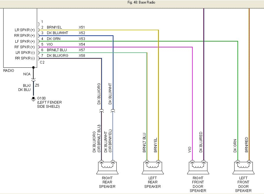
- Colors: Each wire is identified by a color code (e.g., BLU for blue, GRN for green, RED for red, etc.). These colors are crucial for identifying the correct wires in the harness.
- Connectors: Shown as squares or rectangles with numbers inside. The numbers correspond to the pin numbers on the connector.
- Ground Symbols: Indicate where a wire is connected to the vehicle's chassis for grounding. A common symbol is three horizontal lines getting progressively shorter.
- Component Symbols: Represent different components, such as the head unit (often a rectangle with knobs), speakers (circles), and amplifiers (rectangles with amplification symbols).
- Fuses: Showed as a jagged line between the power source and the component it protects. This indicates the circuit is protected by a fuse.
- Splices: Showed as a dot where two or more wires are connected together.
Color Codes: Pay close attention to the color codes. A typical wire might be labeled "BLU/WHT," meaning a blue wire with a white stripe. Always double-check the color codes before cutting or splicing any wires. Discrepancies can lead to serious problems.
How It Works: Tracing the Circuits
Now, let's talk about how the system actually works. The radio system needs power, ground, and input signals to function. The basic flow is as follows:
- Power: The head unit receives power from the vehicle's battery through the ignition switch and a fuse. This power supply is often labelled as "B+" or "Battery".
- Ground: The head unit and other components are grounded to the vehicle's chassis. This provides a return path for the current.
- Antenna Signal: The antenna receives radio signals and sends them to the head unit.
- Audio Signal Processing: The head unit processes the audio signals from the antenna, CD player, or other sources.
- Amplification: The head unit (or a separate amplifier) amplifies the audio signals.
- Speaker Output: The amplified signals are sent to the speakers, which convert them into sound.
The wiring diagram shows the path of each of these signals, allowing you to trace them from one component to another. For example, you can follow the power wire from the battery, through the fuse, to the head unit. You can also trace the speaker wires from the head unit to the individual speakers.
Real-World Use: Troubleshooting Tips
So, how do you use this knowledge in the real world? Here are some common troubleshooting scenarios:
- No Power to the Radio: Check the fuse first. If the fuse is blown, replace it with the same amperage rating. If the fuse keeps blowing, there's likely a short circuit. Use the wiring diagram to trace the power wire and look for any signs of damage or exposed wires. Also verify the ground connection is secure.
- One Speaker Not Working: Check the speaker wiring. Make sure the speaker is properly connected to the head unit (or amplifier). Use a multimeter to check the speaker's resistance. If the speaker is open or shorted, it needs to be replaced. Trace the wire from the speaker to the head unit and check for damage or breaks.
- Distorted Sound: This could be caused by a faulty speaker, a bad amplifier, or a wiring problem. Check the speaker wiring and the amplifier (if equipped). Use a multimeter to check the speaker's resistance.
- Interference: This could be caused by a loose ground connection or a faulty antenna. Check the ground connections and the antenna cable.
Using a Multimeter: A multimeter is your best friend when troubleshooting electrical problems. It allows you to measure voltage, current, and resistance, which can help you pinpoint the source of the problem. Make sure you know how to use a multimeter safely and effectively.
Safety: Handle with Care
Working with automotive electrical systems can be dangerous. Here are some crucial safety precautions:
- Disconnect the Battery: Always disconnect the negative terminal of the battery before working on the electrical system. This will prevent accidental shorts and shocks.
- Identify Airbag Circuits: Airbag circuits are extremely sensitive. Tampering with them can cause the airbags to deploy accidentally, which can be dangerous. If you're not sure about something, consult a professional.
- Use Proper Tools: Use insulated tools to prevent shorts and shocks.
- Never Work Alone: It's always a good idea to have someone nearby in case of an emergency.
Risk of Fire: Short circuits can generate a lot of heat and potentially start a fire. Always be careful when working with electrical wiring and make sure all connections are secure.
Understanding the radio wiring diagram for your Dodge Ram 1500 empowers you to tackle a wide range of electrical tasks. Remember to proceed carefully, double-check your work, and prioritize safety at all times.
We have a comprehensive Dodge Ram 1500 radio wiring diagram file ready for download. This diagram can be a great assistance in visualizing what we just covered. Contact us to download it. Good luck, and happy wrenching!