Colores Diagrama Sensor De Oxigeno 4 Cables
So, you're diving into the world of four-wire oxygen sensors and their wiring diagrams? Excellent! Understanding these diagrams is crucial for troubleshooting engine performance issues, performing modifications, or simply gaining a deeper understanding of your vehicle's emissions system. This isn't just about replacing a part; it's about diagnosing a problem and ensuring your car runs efficiently and cleanly. We're going to break down the Colores Diagrama Sensor De Oxigeno 4 Cables (color diagram of a 4-wire oxygen sensor) in a way that's clear and practical, even if you're not a seasoned electrical engineer. Plus, we have a downloadable diagram available to help you follow along.
Purpose of Understanding Oxygen Sensor Diagrams
Why bother learning about these diagrams? The primary reason is accurate diagnosis and repair. Oxygen sensors play a vital role in your engine's fuel-air ratio, which directly impacts performance, fuel economy, and emissions. A faulty sensor can trigger the dreaded check engine light (CEL) and lead to poor engine performance. Using the diagram allows you to:
- Identify the correct wires: Ensures you're not accidentally shorting something out.
- Test sensor functionality: Knowing the pinout allows you to use a multimeter to check voltages and resistances.
- Trace wiring issues: Find breaks, shorts, or corrosion in the wiring harness.
- Perform modifications: For advanced users, understanding the signal allows for custom tuning or sensor upgrades.
Essentially, it gives you the power to understand what’s happening in your car's exhaust system and make informed decisions about repairs.
Key Specs and Main Parts of a 4-Wire Oxygen Sensor
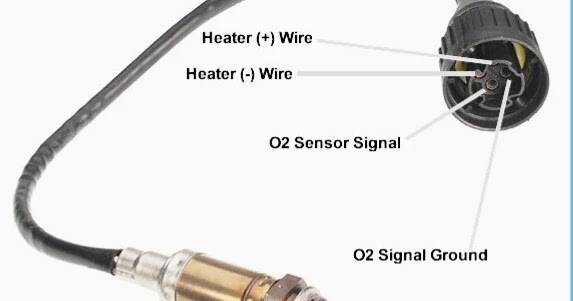
A 4-wire oxygen sensor is a common type used in many modern vehicles. It uses four wires for two primary functions:
- Signal Generation: The sensor measures the amount of oxygen in the exhaust gas and generates a voltage signal proportional to that amount. This signal is sent to the engine control unit (ECU).
- Heating Element: These sensors have an internal heating element to bring the sensor up to operating temperature quickly. This is essential for accurate readings, especially during cold starts.
The main components are:
- Sensing Element (Zirconia or Titania): The core of the sensor, responsible for detecting oxygen levels.
- Heater Element: A resistor that heats the sensing element.
- Electrical Connector: Connects the sensor to the vehicle's wiring harness.
The key specs to look out for include:
- Voltage Range: Typically 0-1V (for zirconia sensors) or 0-5V (for titania sensors).
- Heater Resistance: This will vary depending on the sensor, but a typical range is between 5 and 20 ohms.
- Response Time: How quickly the sensor responds to changes in oxygen levels.
Understanding the Diagram: Symbols, Lines, and Colors
A typical oxygen sensor wiring diagram will show the sensor itself, the wiring harness, and connections to the ECU or other related components. Here's how to interpret the symbols:
Lines:
- Solid Lines: Represent wires.
- Dotted Lines: Sometimes used to indicate shielded wiring or ground connections.
- Arrowheads: Indicate the direction of current flow.
Colors (Colores):
This is where the Colores part of the diagram is crucial. While color coding can vary between manufacturers, here are some common examples:
- Black: Often represents the sensor ground.
- Gray: Often represents the signal ground.
- White: Usually associated with the heater circuit (either positive or negative). Often you will see two white wires for the heater.
- Blue or Yellow: Typically the signal wire (the voltage output from the sensor).
Important Note: *Always* refer to the specific diagram for your vehicle's make and model. Never assume color codes are universal. Consult the manufacturer's repair manual or a reliable online database for the correct information.
Icons:
- Resistor Symbol: Represents the heater element.
- Ground Symbol: Indicates a connection to the vehicle's chassis ground.
- ECU Symbol: A simplified representation of the engine control unit.
How a 4-Wire Oxygen Sensor Works
The sensor works by comparing the amount of oxygen in the exhaust gas to the amount of oxygen in the ambient air. The sensing element (zirconia or titania) generates a voltage based on this difference.
- Zirconia Sensors: Produce a voltage between 0 and 1 volt. A low voltage (near 0V) indicates a lean mixture (high oxygen content), while a high voltage (near 1V) indicates a rich mixture (low oxygen content).
- Titania Sensors: Operate differently; their resistance changes based on oxygen levels. The ECU provides a voltage to the sensor, and the ECU monitors the change in current flow through the sensor.
The heater element is crucial for getting the sensor up to its operating temperature (around 600°F or 315°C) quickly. Without the heater, the sensor would take much longer to reach its optimal temperature, especially during cold starts, leading to inaccurate readings and poor engine performance. The ECU uses the signal from the oxygen sensor to adjust the fuel-air mixture, ensuring optimal combustion and minimizing emissions.
Real-World Use: Basic Troubleshooting Tips
Here are some common troubleshooting scenarios where understanding the wiring diagram is invaluable:
- Check Engine Light (CEL): If you have a CEL related to an oxygen sensor, start by checking the wiring for any obvious damage (cuts, frayed wires, corrosion).
- Testing the Heater Circuit: Use a multimeter to measure the resistance across the heater circuit wires (usually the two white wires). If the resistance is outside the specified range, the heater element is likely faulty.
- Testing the Signal Wire: With the engine running, use a multimeter to measure the voltage on the signal wire (typically blue or yellow). The voltage should fluctuate as the engine's fuel-air mixture changes. A steady voltage or no voltage indicates a problem.
- Verifying Ground Connections: Ensure the ground wires (typically black and gray) have a good connection to the vehicle's chassis. Use a multimeter to check for continuity between the ground wires and a known good ground point on the vehicle.
Don't just replace the sensor right away! Take the time to diagnose the problem properly. A wiring issue or a problem with the ECU can mimic a faulty sensor.
Safety Precautions
Working with automotive electrical systems can be dangerous. Here are some important safety tips:
- Disconnect the Battery: Always disconnect the negative battery terminal before working on any electrical components. This will prevent accidental shorts and potential damage to the ECU.
- Be Careful Around Hot Exhaust: Oxygen sensors are located in the exhaust system, which gets extremely hot. Allow the exhaust system to cool down completely before working on the sensor.
- Use Proper Tools: Use a multimeter designed for automotive use. Make sure your tools are in good condition and properly insulated.
- Avoid Piercing Wires: When testing wires, avoid piercing the insulation whenever possible. Use back-probing techniques or connector breakout boxes to avoid damaging the wiring.
Remember, the oxygen sensor itself can get very hot during operation. Allow sufficient time for it to cool down before handling. Also, working around the exhaust system requires caution to avoid burns.
By understanding the Colores Diagrama Sensor De Oxigeno 4 Cables and following these troubleshooting tips, you'll be well-equipped to diagnose and repair oxygen sensor problems on your vehicle. Remember to always consult your vehicle's specific repair manual for accurate wiring diagrams and specifications.
We have the file available for download, giving you a visual aid to reinforce your understanding of this crucial component.