
Complete Trailer Wiring Kit With Brakes
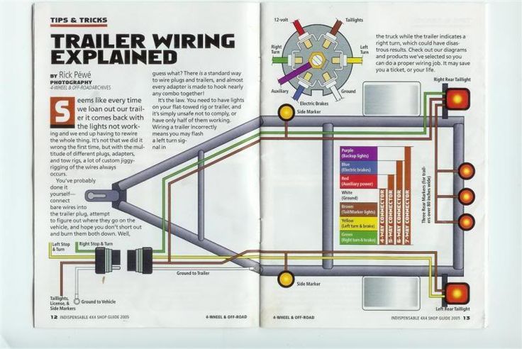
So, you're looking to wire up a trailer with brakes? Excellent choice. Whether you're hauling equipment, boats, or anything else that needs a bit more stopping power, a properly wired trailer brake system is critical for safety and legality. This isn't just about connecting wires; it's about understanding how each component interacts to ensure reliable braking performance. This article will walk you through a complete trailer wiring kit with brakes, focusing on clarity and practical application. We'll cover everything from identifying the key components to troubleshooting common issues.
Purpose – Why This Matters
This guide aims to equip you with the knowledge to confidently install, diagnose, and repair trailer wiring systems with electric brakes. Why is this important? Because a malfunctioning trailer brake can be incredibly dangerous, leading to accidents and legal liabilities. Furthermore, understanding the wiring allows you to:
- Perform DIY repairs: Save money by fixing issues yourself instead of relying on expensive mechanics.
- Upgrade your system: Add new features or replace worn-out components.
- Ensure safety: Properly maintained brakes drastically improve stopping distance and control, especially when hauling heavy loads.
- Understand system limitations: Knowing the ins and outs of your wiring helps you identify potential problems and plan for future upgrades.
Key Specs and Main Parts
Let's break down the essential components of a complete trailer wiring kit with brakes. Knowing these parts and their specifications is fundamental to understanding the system.
- 7-Way RV Blade Connector (Vehicle Side): This is the standard connector that mounts to your tow vehicle. It provides connections for various functions, including:
- Running lights (tail lights, side marker lights)
- Brake lights
- Turn signals (left and right)
- Electric brakes
- Auxiliary power (usually for charging a trailer battery)
- Reverse lights
- Ground
- 7-Way RV Blade Connector (Trailer Side): This mates with the vehicle-side connector and is wired into the trailer's electrical system.
- Wiring Harness: This is the bundle of wires connecting all the components. The gauge (thickness) of the wires is crucial. For brake circuits, 12-gauge wire is typically recommended for shorter trailers (under 25 feet), while 10-gauge is preferred for longer trailers to minimize voltage drop. Lights and other circuits usually use 14- or 16-gauge wire.
- Electric Brake Controller: This device, mounted in the tow vehicle, sends electrical current to the trailer brakes. It typically has adjustable gain settings to control the braking force. Modern controllers often use inertia sensors or accelerometers to proportionally apply the brakes based on the tow vehicle's deceleration.
- Brake Magnets: These are located inside the brake drums of the trailer axles. When energized by the brake controller, the magnet is pulled against the armature plate, creating friction that actuates the brakes. Brake magnet size (diameter) and current draw are crucial specifications; incorrect magnets will lead to poor brake performance.
- Junction Box (Optional, but recommended): This box provides a central location to connect all the trailer wiring. It simplifies troubleshooting and allows for cleaner wiring.
- Breakaway Kit: This is a mandatory safety device. It consists of a small battery, a switch, and a cable that attaches to the tow vehicle. If the trailer becomes detached, the cable pulls the pin on the switch, activating the trailer brakes, and stopping the trailer as quickly as possible.
Symbols – Understanding the Wiring Diagram
A wiring diagram is essentially a roadmap for your electrical system. Understanding the symbols is crucial for interpreting and using the diagram effectively. Here's a breakdown of common symbols:
- Solid Lines: Represent wires. The thickness may (but not always) indicate the wire gauge.
- Dotted Lines: Often represent ground connections or shielded cables.
- Colors: Each wire is color-coded. Standard colors are used to represent specific functions (e.g., brown for running lights, blue for electric brakes). The color code can vary slightly depending on the manufacturer, so always refer to the diagram for confirmation.
- Circles with Numbers or Letters: Represent connection points or terminals. These are often labeled to indicate the function of the connection (e.g., "LT" for left turn, "RB" for right brake).
- Rectangles: Typically represent components like lights, switches, and relays.
- Ground Symbol (⏚): Indicates a connection to the vehicle's chassis or frame, providing a return path for the electrical current. A good, clean ground is essential for proper circuit operation.
- Fuse Symbol: Indicates a fuse, which protects the circuit from overcurrent.
How It Works
The system works as follows:
- When you apply the brakes in the tow vehicle, the brake controller senses the deceleration.
- The brake controller sends an electrical signal to the 7-way connector.
- This signal travels through the trailer wiring harness to the brake magnets inside the trailer brake drums.
- The brake magnets are energized, creating a magnetic field that attracts them to the armature plate.
- This attraction causes friction, which applies the trailer brakes.
- The amount of braking force is proportional to the signal from the brake controller, which is determined by the deceleration of the tow vehicle and the gain setting of the controller.
- Other circuits, such as running lights, brake lights, and turn signals, are activated by their respective switches in the tow vehicle and travel through the 7-way connector to the trailer.
The breakaway system is independent. If the trailer separates from the tow vehicle, the breakaway cable pulls the pin on the breakaway switch, activating the trailer brakes using the breakaway battery, bringing the trailer to a stop.
Real-World Use – Basic Troubleshooting Tips
Even with careful installation, problems can arise. Here are some common issues and troubleshooting tips:
- No Trailer Brakes:
- Check the brake controller settings and connections.
- Inspect the 7-way connector for corrosion or damage.
- Test the brake magnets with a multimeter to ensure they are drawing current.
- Check the wiring for shorts or open circuits.
- Inspect the breakaway switch and battery.
- Lights Not Working:
- Check the bulbs and connections.
- Inspect the 7-way connector for corrosion or damage.
- Check the ground connection.
- Test the wiring with a multimeter to identify any open circuits.
- Brakes Locking Up:
- Reduce the gain setting on the brake controller.
- Inspect the brake magnets for excessive wear or damage.
- Check the wiring for shorts or voltage spikes.
- Weak Brakes:
- Increase the gain setting on the brake controller.
- Inspect the brake magnets for wear.
- Ensure proper adjustment of the brake shoes.
- Check for proper voltage at the brake magnets while braking.
Always use a multimeter to test circuits. Never assume a wire is good based on visual inspection alone. Remember to disconnect the battery before working on any electrical components.
Safety – Highlight Risky Components
Working with electrical systems always presents risks. Pay close attention to these components:
- Brake Controller: Incorrect installation or settings can lead to over-braking or under-braking, both of which are dangerous. Always follow the manufacturer's instructions carefully.
- Brake Magnets: These can get very hot during operation. Avoid touching them immediately after use.
- Breakaway Battery: Handle with care. Although usually sealed, damage could cause leakage of corrosive materials.
- Wiring: Short circuits can cause fires. Always use properly sized wiring and protect it from abrasion and damage. Route wiring away from sharp edges and hot exhaust components.
Always disconnect the battery before working on any wiring to prevent accidental shorts.
It is extremely crucial to ensure all connections are sound and weatherproofed to prevent corrosion, which can lead to unreliable performance and potential safety hazards.
Remember, trailer wiring is a critical aspect of safe towing. If you're uncomfortable with any part of the process, consult a qualified professional.
We have a detailed wiring diagram available for download to further assist you with your project. It includes specific wire colors, terminal assignments, and troubleshooting tips.