Connector 3 Wire Nissan Alternator Wiring Diagram
Alright, let's dive into the 3-wire Nissan alternator wiring diagram. Understanding this setup is crucial whether you're tackling a repair, upgrading your charging system, or just expanding your automotive knowledge. We're going to break down the diagram, covering everything from its purpose to some basic troubleshooting. Think of this as your comprehensive guide to navigating the often-intimidating world of automotive electrical systems, specifically the Nissan 3-wire alternator.
Purpose of Understanding the 3-Wire Nissan Alternator Wiring Diagram
Why bother with a wiring diagram? Several reasons come to mind. First, it's essential for accurate diagnosis. If your battery isn't charging correctly, or you suspect a faulty alternator, the diagram allows you to trace circuits and pinpoint the problem area. Second, it's invaluable for repairs. Replacing damaged wiring, connectors, or even the alternator itself becomes much safer and more efficient when you know exactly what goes where. Third, for those involved in modifications, like installing a higher-output alternator or integrating it into a non-Nissan vehicle, the diagram is absolutely critical for proper integration. Finally, simply learning how the system works makes you a more informed and capable car owner.
Key Specifications and Main Parts
Before we delve into the diagram, let's outline the key components involved in the 3-wire Nissan alternator setup. We need to identify the parts before we can diagnose their wiring.
- Alternator: This is the heart of the charging system. It converts mechanical energy from the engine into electrical energy to charge the battery and power the vehicle's electrical loads.
- Voltage Regulator: This component, often integrated into the alternator, regulates the output voltage to prevent overcharging and damage to the battery and other electrical components. Most 3-wire alternators are internally regulated.
- Battery: The battery stores electrical energy and provides power to start the engine and run accessories when the engine is off.
- Fuses and Fusible Links: These are safety devices designed to protect the electrical system from overcurrent conditions. They are essential to prevent fires.
- Wiring Harness: This is the network of wires that connects all the electrical components in the system.
- Connectors: These provide secure and reliable connections between wires and components. The specific connector for the alternator is, obviously, critical.
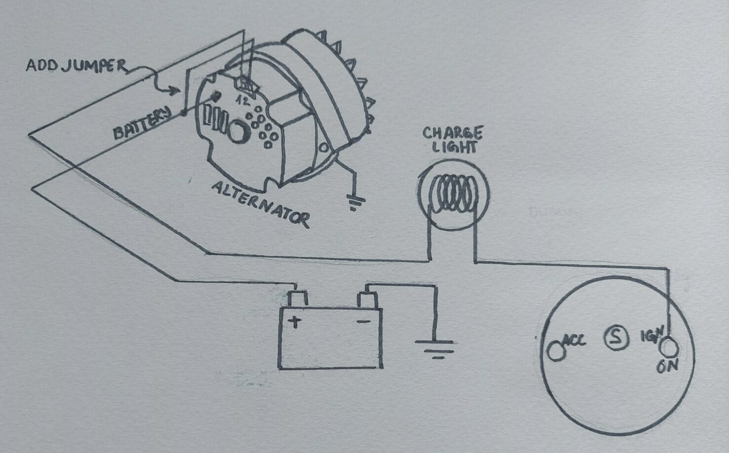
The "3-wire" designation refers to the three wires connected to the alternator. Let's identify them:
- B+ (Battery Positive): This is the main output wire that carries the charging current from the alternator to the battery positive terminal. This is often a heavy-gauge wire.
- Ignition (or "Sense") Wire: This wire connects to a switched ignition source. It tells the alternator when the engine is running and to start charging. It often acts as a remote voltage sensing wire, measuring the voltage closer to the car's electric components.
- Lamp (or "Stator") Wire: This wire connects to the charge indicator lamp (battery light) in the instrument cluster. It provides a ground path for the lamp when the alternator is not charging, illuminating the warning light. Once the alternator starts charging, this wire provides a positive voltage, turning off the light.
Understanding the Symbols in the Wiring Diagram
A wiring diagram is a symbolic representation of the electrical system. Understanding these symbols is crucial for interpreting the diagram correctly.
- Lines: Lines represent wires. The thickness of the line may indicate the wire gauge (thicker lines for higher current carrying capacity).
- Colors: Each wire is typically identified by a color code (e.g., Red, Blue, Black). The diagram will include a key that lists the color codes and their corresponding functions.
- Connectors: Connectors are represented by various shapes, such as circles, squares, or rectangles, often with numbered pins. The diagram will indicate the connector type and pin configuration.
- Fuses: Fuses are represented by a symbol that looks like a small resistor or a wavy line inside a box. The amperage rating of the fuse is usually indicated next to the symbol.
- Ground: The ground symbol looks like a series of stacked horizontal lines, decreasing in length.
- Alternator: Typically represented by a circle with specific labeling for the terminals (B+, Ignition, Lamp).
- Battery: Represented by a series of long and short parallel lines, with a "+" symbol for positive and a "-" symbol for negative.
Important Note: Nissan wiring diagrams often use abbreviations for wire colors. You might see "W" for White, "B" for Black, "R" for Red, "G" for Green, "L" for Blue (often Lt. Blue), and "Y" for Yellow. Refer to the diagram's key for a complete list.
How the 3-Wire Nissan Alternator System Works
Here's a simplified explanation of how the system operates:
- When the ignition key is turned to the "ON" position, the ignition wire provides power to the voltage regulator inside the alternator.
- The voltage regulator sends a small current through the lamp wire to ground, completing the circuit and illuminating the battery warning light on the dashboard.
- When the engine starts, the alternator begins to spin, generating voltage.
- Once the alternator voltage exceeds the battery voltage, the voltage regulator switches the lamp wire from ground to a positive voltage. This equalizes the voltage across the bulb and extinguishes the battery warning light.
- The alternator then begins charging the battery through the B+ wire. The voltage regulator continuously monitors the battery voltage and adjusts the alternator's output to maintain a constant voltage, typically around 13.8-14.4 volts.
- The 'Sense' wire, connected to the ignition source, provides a voltage reference closer to the vehicle's electrical loads. This allows the voltage regulator to compensate for voltage drop in the wiring, ensuring that the battery and electrical components receive the correct voltage.
Real-World Use: Basic Troubleshooting Tips
Let's consider some common issues and how the wiring diagram can help you troubleshoot them.
- Battery Light Stays On: This could indicate a faulty alternator, a broken belt, or a problem with the lamp wire. Use the diagram to check the continuity of the lamp wire and verify that it's properly connected to the instrument cluster and the alternator.
- Battery Not Charging: Check the B+ wire for continuity and secure connections. Inspect the fuse or fusible link in the B+ circuit. Verify that the ignition wire is receiving power when the ignition is switched on. A multimeter is your best friend here.
- Overcharging: This is usually caused by a faulty voltage regulator. While less common in internally regulated alternators, it can still happen. Replacing the alternator is often the only solution. Use the diagram to verify the voltage regulator wiring.
- Intermittent Charging Problems: These can be tricky to diagnose. Check all connections for corrosion or looseness. A voltage drop test along the B+ and ground wires can help identify areas of high resistance.
Safety Considerations
Working with electrical systems can be dangerous. Always disconnect the battery's negative terminal before working on the electrical system. Be particularly cautious when working with the B+ wire, as it carries high current. Never short-circuit the B+ wire to ground, as this can damage the alternator and other electrical components. Wear appropriate safety gear, such as safety glasses and insulated gloves.
Disclaimer: Always consult your vehicle's specific repair manual and wiring diagram for the most accurate and up-to-date information. The information provided here is for general guidance only and should not be considered a substitute for professional advice.
High-Risk Components: The B+ terminal and any exposed wiring connected directly to the battery are high-risk components. A short circuit here can cause a fire. Exercise extreme caution when working in these areas.
We have the complete wiring diagram file available. Just let us know and we can get it to you.