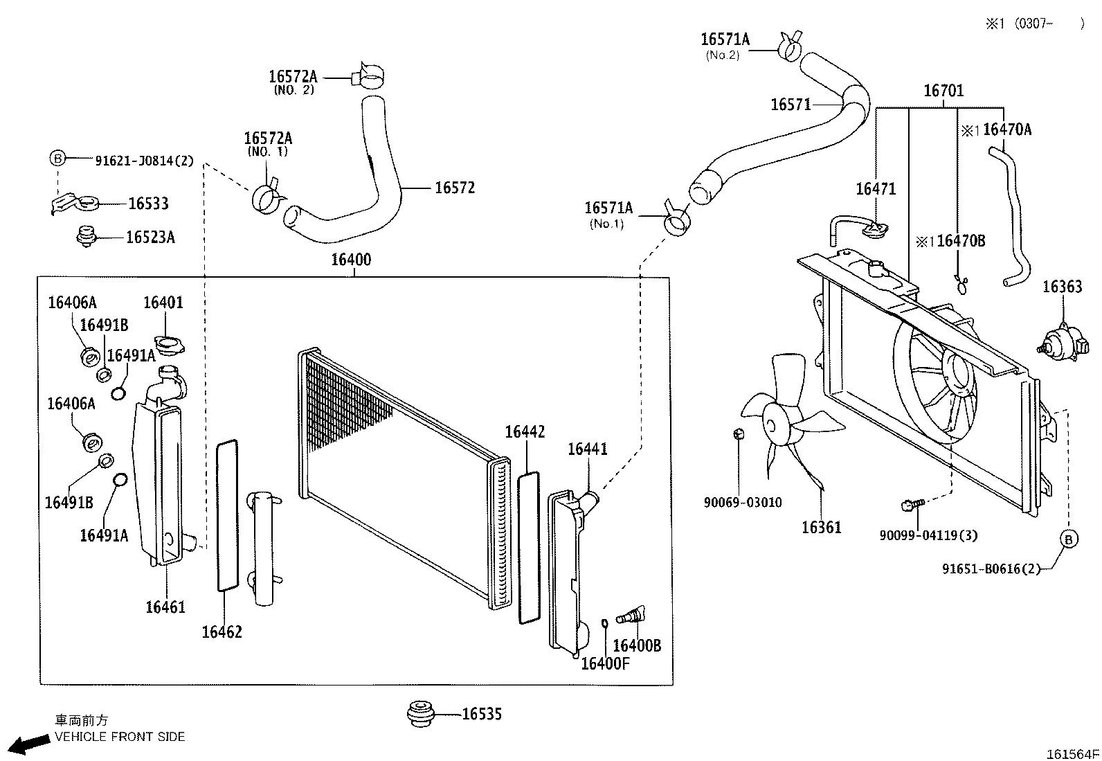
Coolant System Toyota Corolla Cooling System Diagram
Understanding the cooling system of your Toyota Corolla is crucial for maintaining its longevity and performance. A cooling system diagram serves as a roadmap, enabling informed maintenance, accurate troubleshooting, and even performance modifications. This guide will walk you through interpreting a typical Corolla cooling system diagram, equipping you with the knowledge to diagnose issues and perform repairs with confidence. We'll cover the key components, symbols, operational principles, and safety considerations, all geared toward the experienced DIYer.
Purpose of the Cooling System Diagram
Why bother with a diagram? Think of it as the blueprint to your engine's temperature regulation. It allows you to:
- Diagnose Problems: Trace leaks, identify faulty components (e.g., a thermostat stuck closed), and understand the flow of coolant when diagnosing overheating or underheating issues.
- Perform Repairs: Locate components for replacement, understand the order of assembly, and ensure correct hose routing, preventing kinks and leaks.
- Plan Modifications: If you're considering upgrades like a larger radiator or an auxiliary cooler (for, say, transmission fluid), the diagram helps you plan the integration and ensure compatibility.
- General Understanding: Simply knowing how the system works empowers you to be a more proactive owner and spot potential problems early.
Key Specs and Main Parts
A typical Toyota Corolla cooling system comprises several critical components, each with a specific function:
- Radiator: The primary heat exchanger, dissipating heat from the coolant into the atmosphere. Specifications to note include its core dimensions (height, width, thickness), construction material (aluminum or copper/brass), and cooling capacity (often expressed in BTU/hr).
- Water Pump: Circulates coolant throughout the engine and cooling system. It's usually belt-driven but can be electric on some models. Specs include flow rate (gallons per minute - GPM) and operating pressure.
- Thermostat: A temperature-sensitive valve that regulates coolant flow to the radiator, maintaining a consistent engine operating temperature. The most critical spec is its opening temperature (e.g., 180°F or 82°C).
- Coolant Reservoir (Expansion Tank): Accommodates coolant expansion and contraction due to temperature changes. It often includes markings for "MIN" and "MAX" coolant levels.
- Hoses: Connect all the components, carrying coolant throughout the system. Different hoses handle different pressures and temperatures. Material (e.g., EPDM rubber, silicone) is a key specification.
- Cooling Fan: Enhances airflow through the radiator, especially at low speeds or when idling. Can be mechanically driven (belt-driven) or electrically driven. Electric fans often have multiple speeds.
- Pressure Cap: Maintains pressure within the system, raising the boiling point of the coolant. The pressure rating (e.g., 16 psi) is crucial for proper system operation.
- Engine Block and Cylinder Head Water Jackets: Internal passages within the engine where coolant circulates to absorb heat.
- Heater Core: A small radiator located inside the vehicle's HVAC system that provides heat to the cabin.
Symbols and Interpretation
Understanding the symbols used in a cooling system diagram is vital for accurate interpretation:
- Solid Lines: Typically represent coolant hoses or pipes carrying liquid coolant. Line thickness can sometimes indicate hose diameter or flow rate.
- Dotted Lines: Often denote vacuum lines or connections for sensors.
- Arrows: Indicate the direction of coolant flow. Follow these carefully to understand the coolant's path through the system.
- Colors: While not always standardized, some diagrams use color coding. For example, blue might represent cooler coolant returning to the engine, while red represents hot coolant exiting the engine.
- Component Symbols: Each component has a representative symbol. For instance, a radiator is usually depicted as a rectangular grid, a water pump as a circular shape with blades, and a thermostat as a valve symbol. Consult a legend if one is provided.
How It Works
The Corolla's cooling system operates on a closed-loop principle. Here's a simplified breakdown:
- The water pump circulates coolant from the bottom of the radiator, through the engine block and cylinder head water jackets.
- As the coolant flows through the engine, it absorbs heat generated by combustion.
- The heated coolant exits the engine and flows towards the thermostat.
- If the engine is cold, the thermostat remains closed, diverting coolant back to the water pump for recirculation within the engine (bypassing the radiator). This allows the engine to warm up quickly to its optimal operating temperature.
- Once the engine reaches its operating temperature (defined by the thermostat's opening temperature), the thermostat begins to open, allowing hot coolant to flow to the radiator.
- As coolant passes through the radiator's core, heat is dissipated into the atmosphere, aided by airflow from the cooling fan.
- The cooled coolant then returns to the water pump to repeat the cycle.
- The coolant reservoir accommodates the expansion and contraction of the coolant as its temperature fluctuates.
- The heater core receives hot coolant, providing heat to the vehicle's cabin via the HVAC system.
Real-World Use: Basic Troubleshooting
Here are some common cooling system problems and how the diagram can help with diagnosis:
- Overheating: Use the diagram to check coolant flow. Is the thermostat opening? Is the water pump functioning? Are there any blockages in the hoses or radiator? Examine the fan operation - is it running properly?
- Coolant Leaks: The diagram helps pinpoint the location of leaks. Trace the coolant path to identify damaged hoses, connections, or components. Look for telltale signs of dried coolant.
- No Heat in Cabin: Check the heater core hoses and the heater control valve (if equipped). The diagram will show their location and routing. A blocked heater core or a faulty valve can prevent hot coolant from reaching the core.
- Coolant Loss: Use the diagram to understand the entire system to check for leaks in the various areas that are related to the system such as hoses, radiator, water pump and engine block/head.
Safety Considerations
Working on the cooling system involves potential hazards. Keep these points in mind:
- Hot Coolant: Never remove the radiator cap or loosen hoses while the engine is hot. The system is pressurized, and scalding hot coolant can erupt, causing severe burns. Allow the engine to cool completely before working on the system.
- Electric Fans: Disconnect the negative battery cable before working near the cooling fan, especially if it's electrically driven. The fan can activate unexpectedly, causing injury.
- Coolant Disposal: Coolant is toxic. Dispose of used coolant properly at a recycling center. Do not pour it down the drain or onto the ground.
- Pressure Cap: Handle the pressure cap with care. Inspect it for damage and replace it if necessary. A faulty pressure cap can lead to leaks and overheating.
Remember to consult your vehicle's repair manual for specific diagrams and instructions related to your particular Corolla model and engine. While the general principles remain the same, there might be variations in component placement and hose routing.
We have a detailed cooling system diagram for common Toyota Corolla models available for download. Contact us to get access to the file!