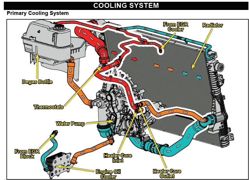
Cooling System Ford 4.6 Coolant Flow Diagram
Understanding the coolant flow diagram for your Ford 4.6L engine is crucial for diagnosing cooling system issues, performing maintenance, and even planning performance upgrades. This isn't just a pretty picture; it's a roadmap of how your engine stays within its optimal operating temperature. This article breaks down the diagram, explains the key components, and provides practical troubleshooting tips.
Why Bother with the Coolant Flow Diagram?
Let's face it: cooling systems can be complex. A coolant flow diagram provides a visual representation of the system's layout, making it easier to:
- Diagnose Overheating: Identify potential blockages, faulty components, or leaks based on how coolant should be circulating.
- Perform Maintenance: Understand the proper coolant drain and fill procedures, and locate bleed points for removing air pockets.
- Plan Modifications: When installing aftermarket parts like larger radiators, performance water pumps, or oil coolers, knowing the coolant flow path is essential for proper integration.
- Troubleshoot Heater Issues: The diagram shows how coolant is routed to the heater core, helping you pinpoint problems with heat output.
Key Specs and Main Parts of the Ford 4.6L Cooling System
The Ford 4.6L engine (found in Mustangs, Crown Victorias, Explorers, and more) utilizes a pressurized cooling system, typically operating between 13-16 PSI (pounds per square inch) depending on the model and year. Here's a rundown of the key components depicted in the diagram:
- Radiator: The primary heat exchanger. Coolant flows through the radiator core, transferring heat to the surrounding air, which is then dissipated by the radiator fan. Key specs include core thickness, fin density, and material (aluminum vs. copper/brass).
- Water Pump: Circulates coolant throughout the engine and cooling system. The diagram shows its location on the engine block and its connection to the coolant passages. Specifications to note include flow rate (gallons per minute or GPM) and impeller design. A failing water pump is a common cause of overheating.
- Thermostat: A temperature-sensitive valve that regulates coolant flow to the radiator. It opens at a specific temperature (typically 180-195°F or 82-91°C) to allow coolant to flow through the radiator when the engine reaches operating temperature. A stuck-closed thermostat is a very common cause of overheating.
- Thermostat Housing: Encloses the thermostat and provides a connection point for coolant hoses.
- Coolant Hoses: Flexible hoses that connect the various components of the cooling system. Pay attention to the hose routing in the diagram.
- Heater Core: A small radiator located inside the passenger compartment that provides heat. Coolant flows through the heater core, and a fan blows air across it, warming the cabin.
- Heater Hoses: Hoses that connect the engine coolant passages to the heater core.
- Coolant Reservoir (Overflow Tank): Stores excess coolant and allows for expansion and contraction as the coolant temperature changes. It also allows air to bleed from the system.
- Pressure Cap: Maintains pressure within the cooling system, raising the boiling point of the coolant. A faulty pressure cap can lead to coolant loss and overheating.
- Engine Coolant Passages: Internal passages within the engine block and cylinder heads that allow coolant to circulate around the cylinders and other critical components, absorbing heat.
Decoding the Coolant Flow Diagram: Symbols and Conventions
Understanding the symbols used in the diagram is crucial for interpreting it correctly. While specific diagrams may vary slightly, these are the most common conventions:
- Solid Lines: Generally represent coolant hoses and pipes. The thickness of the line might indicate the diameter of the hose.
- Dashed Lines: May represent vacuum lines, sensor wiring, or internal coolant passages within the engine block or cylinder heads.
- Arrows: Indicate the direction of coolant flow. Follow the arrows to trace the path of the coolant through the system.
- Colors: While not always present, colors can be used to distinguish between different types of fluids (e.g., coolant vs. oil).
- Component Symbols: Each component is represented by a stylized symbol. Radiators are typically shown as a rectangular grid, water pumps as a circle with an impeller, and thermostats as a valve. Look for a legend or key on the diagram to identify each symbol.
How the Ford 4.6L Cooling System Works
Here's a simplified explanation of the coolant flow path:
- The water pump, driven by the engine's accessory belt, draws coolant from the bottom of the radiator.
- The coolant is then pumped through the engine block and cylinder heads, absorbing heat generated by combustion.
- The heated coolant flows past the thermostat. If the engine is below its operating temperature, the thermostat remains closed, and the coolant is recirculated back to the water pump through a bypass passage, allowing the engine to warm up quickly.
- Once the engine reaches its operating temperature, the thermostat opens, allowing coolant to flow to the radiator.
- In the radiator, the coolant releases heat to the air passing through the radiator core.
- The cooled coolant returns to the water pump to repeat the cycle.
- A portion of the coolant is also routed to the heater core to provide cabin heat.
- The coolant reservoir accommodates expansion and contraction of the coolant and allows air to be purged from the system.
Real-World Troubleshooting with the Coolant Flow Diagram
The diagram can be invaluable for troubleshooting common cooling system problems:
- Overheating: Use the diagram to check for potential blockages in the coolant flow path. Examine the radiator hoses for kinks or collapses, and check the thermostat for proper operation. A non-functioning water pump is another potential culprit.
- Coolant Leaks: Trace the coolant flow path to identify potential leak sources. Check hose connections, the water pump seal, the thermostat housing, and the radiator for signs of leakage.
- No Heat: If you're not getting heat in the cabin, check the heater hoses for blockages or kinks. Also, verify that the heater control valve (if equipped) is functioning correctly. The diagram will show you the heater core's location and hose routing.
- Erratic Temperature Readings: A faulty thermostat can cause erratic temperature readings. The diagram will show the thermostat's location, making it easier to access for testing or replacement.
Safety First: Important Considerations
Caution: Never work on a cooling system when the engine is hot. Coolant is under pressure and can cause severe burns. Allow the engine to cool completely before opening the system.
- Pressure Cap: The pressure cap is a critical component that maintains pressure within the system. A faulty cap can release pressure prematurely, leading to coolant loss and overheating. Always use a new, high-quality pressure cap when replacing one.
- Hot Coolant: As mentioned above, hot coolant can cause severe burns. Wear gloves and eye protection when working on the cooling system.
- Sharp Edges: Be careful of sharp edges on the radiator fins and other cooling system components.
- Electrical Components: Avoid getting coolant on electrical connectors or wiring.
By understanding the coolant flow diagram and the function of each component, you'll be well-equipped to diagnose and repair cooling system issues on your Ford 4.6L engine. Remember to always prioritize safety and consult a professional if you're unsure about any procedure.
We have a detailed coolant flow diagram available for download. This diagram provides a visual representation of the cooling system, making it easier to understand the flow of coolant and identify potential problems. Please contact us to request the file.