Cooling System Northstar Engine Coolant Flow Diagram
Understanding the coolant flow in a Northstar engine is crucial for anyone tackling repairs, modifications, or even just routine maintenance. The Northstar, known for its complexity and sensitivity to overheating, demands a deep understanding of its cooling system to ensure longevity and optimal performance. This article dives into the specifics of a typical Northstar engine coolant flow diagram, equipping you with the knowledge to interpret it effectively.
Why This Diagram Matters
A coolant flow diagram is more than just a pretty picture; it's a roadmap to your engine's thermal management system. Specifically, for a Northstar, understanding the coolant flow is *essential* for several reasons:
- Diagnostics: Identifying clogs, leaks, or malfunctioning components becomes much easier when you know the expected flow path.
- Repairs: Knowing where coolant is supposed to go allows you to pinpoint the source of overheating issues or identify parts that might be impeding flow.
- Modifications: Planning engine modifications, especially those affecting heat output, requires an understanding of the cooling system's capacity and flow dynamics.
- Maintenance: Proper coolant flushing and system bleeding are much easier when you understand the flow path. You'll know where to connect your flushing equipment and which bleed points to use.
- Learning: Simply studying the diagram helps you grasp the complexity of the Northstar engine's thermal management, which is a great foundation for future repair projects.
Key Specs and Main Parts of the Northstar Cooling System
Before we dive into the diagram, let's review the core components and some typical specifications (which may vary slightly depending on the specific Northstar generation and vehicle).
Main Components:
- Radiator: The primary heat exchanger, dissipating heat from the coolant to the atmosphere.
- Water Pump: Circulates coolant throughout the engine block, cylinder heads, and radiator. The Northstar typically uses a belt-driven water pump.
- Thermostat: Regulates coolant temperature by controlling the flow of coolant to the radiator. Typical thermostat operating temperatures range from 180-195°F (82-91°C).
- Coolant Reservoir (Expansion Tank): Allows for coolant expansion and contraction due to temperature changes, maintaining system pressure and preventing airlocks.
- Heater Core: A small radiator located in the vehicle's dashboard, providing heat to the passenger compartment.
- Coolant Hoses: Connect all the components, facilitating coolant flow.
- Coolant Temperature Sensors (CTS): Provide temperature readings to the ECU for engine management and diagnostics.
- Coolant Passages: Internal passages within the engine block and cylinder heads that direct coolant flow.
Key Specifications (Examples):
- Coolant Capacity: Varies, but typically around 12-14 quarts (11-13 liters). Always consult your vehicle's service manual.
- Coolant Type: Typically uses Dex-Cool (OAT - Organic Acid Technology) coolant. Never mix different types of coolant!
- Operating Temperature: Normal operating temperature is usually between 195-220°F (91-104°C).
- Pressure Cap: Maintains system pressure, typically around 15-18 PSI.
Understanding the Symbols in the Diagram
Coolant flow diagrams use a standardized set of symbols to represent various components and the direction of coolant flow. Here's a breakdown of common symbols:
- Solid Lines: Represent coolant hoses or passages. Line thickness can sometimes indicate hose diameter.
- Dotted Lines: Often represent vacuum lines or secondary coolant lines (e.g., overflow tubes).
- Arrows: Indicate the direction of coolant flow. Pay close attention to these!
- Rectangles: Typically represent the radiator, heater core, or coolant reservoir.
- Circles: Can represent the water pump, thermostat housing, or sensors.
- Diamond/Rounded Rectangle: Typically represents the engine block or cylinder heads.
- Color Coding (if present): Usually indicates temperature zones. For example, red might represent hot coolant exiting the engine, while blue represents cooler coolant returning from the radiator. Note that color coding is not always standardized across diagrams.
It's crucial to remember that diagrams can vary slightly depending on the specific vehicle model and year. Always refer to the diagram specific to your Northstar engine.
How the Coolant Flow Works in a Northstar Engine
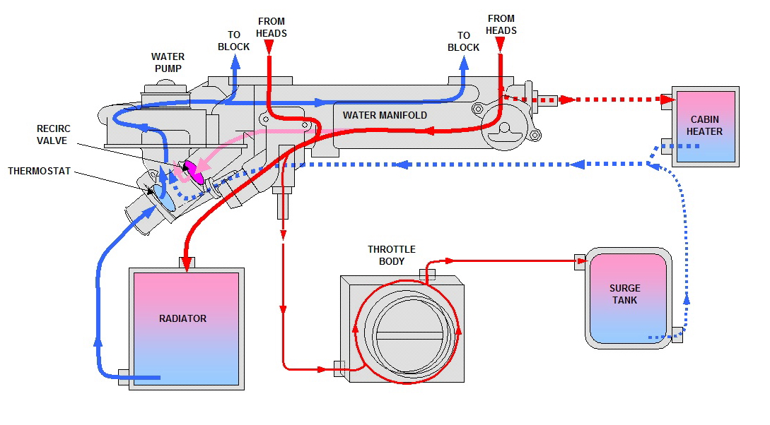
Here's a generalized description of the coolant flow in a typical Northstar engine, based on a typical diagram:
- Water Pump Intake: The water pump draws coolant from the bottom of the radiator (after it's been cooled) or, when the thermostat is closed, from a bypass passage in the engine block.
- Engine Block Circulation: The pump forces the coolant through the engine block, absorbing heat generated by combustion. Northstar engines have complex internal coolant passages to evenly distribute coolant around the cylinders.
- Cylinder Head Circulation: From the engine block, the coolant flows into the cylinder heads, absorbing heat from the combustion chambers and valves. The Northstar, with its overhead cam design, requires efficient cooling of the cylinder heads.
- Thermostat Housing: The heated coolant exits the cylinder heads and flows to the thermostat housing.
- Thermostat Regulation:
- Thermostat Closed (Engine Cold): The thermostat blocks coolant flow to the radiator, redirecting it through a bypass passage back to the water pump. This allows the engine to warm up quickly.
- Thermostat Open (Engine Hot): As the engine reaches its operating temperature, the thermostat opens, allowing coolant to flow to the radiator.
- Radiator Cooling: Coolant flows through the radiator core, where heat is dissipated to the atmosphere via airflow (natural or from the cooling fans).
- Return to Water Pump: The cooled coolant exits the radiator and returns to the water pump, completing the cycle.
- Heater Core Loop: A separate loop allows coolant to flow through the heater core, providing heat to the passenger compartment. This loop usually draws coolant from the engine block and returns it to the water pump or a radiator hose.
- Coolant Reservoir: The coolant reservoir is connected to the radiator or a coolant hose, allowing for expansion and contraction of the coolant as its temperature changes. It also acts as a low-pressure vent.
Real-World Use: Basic Troubleshooting
Using the coolant flow diagram, you can troubleshoot common cooling system problems:
- Overheating: If the engine overheats, check the diagram to ensure coolant is flowing through the radiator. Verify the thermostat is opening and that the water pump is functioning. Look for blockages in hoses or the radiator core.
- Coolant Leaks: Trace the coolant flow to identify the source of the leak. Check hose connections, the water pump seal, and the radiator core.
- No Heat in Cabin: Check the heater core hoses for blockages or kinks. Verify that coolant is flowing through the heater core circuit. Check the blend door actuator which controls the air flow mix between the heater core and the A/C evaporator.
- Coolant Loss: Check for leaks at all connections and components. Inspect the coolant reservoir for cracks. A pressure test can help reveal hidden leaks.
- Air Pockets: The Northstar engine is notorious for trapping air in its cooling system. Use the diagram to locate the bleeder valves and properly bleed the system after any work on the cooling system. Consult your service manual for the correct bleeding procedure.
Always consult your vehicle's service manual for specific troubleshooting procedures and torque specifications.
Safety Precautions
Working with the cooling system can be dangerous. Hot coolant can cause severe burns.
- Never open the radiator cap or coolant reservoir cap when the engine is hot. Allow the engine to cool completely before working on the system.
- Wear safety glasses and gloves when working with coolant.
- Dispose of used coolant properly. It is toxic to the environment and to animals.
- Be careful when working around the cooling fans. Ensure they are not running before putting your hands near them. It's advisable to disconnect the negative battery terminal for safety.
The water pump and thermostat areas can be particularly risky when the engine is hot. Exercise extreme caution in these areas.
With a good understanding of the coolant flow diagram and proper safety precautions, you can effectively diagnose and repair cooling system problems on your Northstar engine, keeping it running smoothly for years to come.
We have a detailed coolant flow diagram that you can download. Contact us for the file.