Crankcase Ventilation System Diagram
Alright, let's dive into the crankcase ventilation system. If you're looking to understand your engine better, perform some upgrades, or even just troubleshoot a pesky oil leak, understanding this system is crucial. We're going to break down a typical crankcase ventilation system diagram, giving you the knowledge to interpret it and apply that knowledge to your own vehicle. Knowing how it works empowers you to perform maintenance and even improve your engine's performance. And to help you even more, we have a high-resolution diagram that you can download at the end of this article.
Why Bother with a Crankcase Ventilation System Diagram?
Think of the crankcase ventilation system diagram as a roadmap for understanding the air and pressure flow within your engine's crankcase. It's not just some abstract drawing; it's a key tool for:
- Troubleshooting: Identifying the root cause of issues like oil leaks, poor performance, or even a check engine light. A clogged PCV valve or a cracked hose can throw everything off.
- Maintenance: Knowing where components are located and how they interconnect makes routine maintenance, like PCV valve replacement, much easier.
- Performance Upgrades: If you're considering modifications to your engine, understanding the crankcase ventilation system is vital to ensure you're not negatively impacting its function. For example, adding boost requires careful attention to crankcase pressure.
- General Engine Understanding: Simply knowing how your engine breathes contributes to a better understanding of its overall operation.
Key Specs and Main Parts
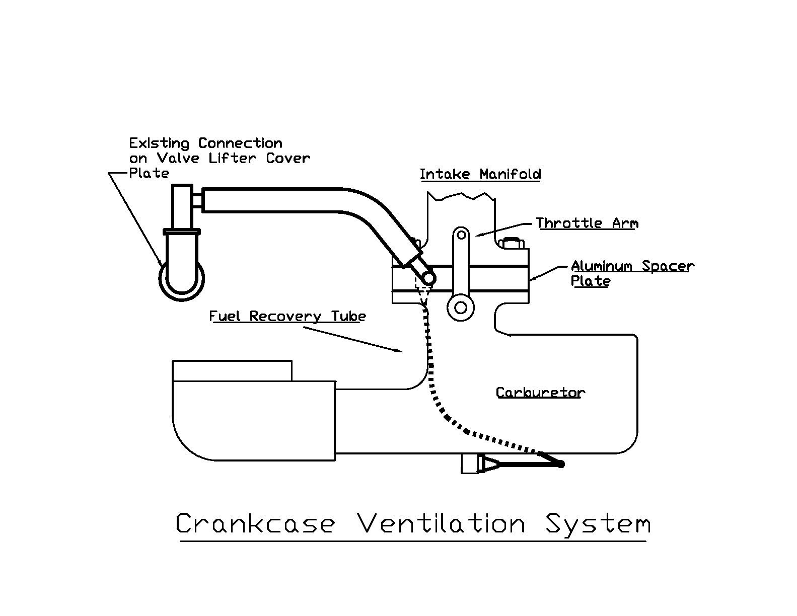
A typical crankcase ventilation system, often called the PCV (Positive Crankcase Ventilation) system, consists of the following key components. These will be clearly identified in the diagram:
- Crankcase: This is the heart of the engine where the crankshaft spins. This is where the blow-by gases originate.
- PCV Valve: The crucial component that regulates the flow of crankcase gases into the intake manifold. It's designed to only allow flow in one direction and to control the amount of flow based on engine vacuum.
- Intake Manifold: The distribution center for air entering the engine. The PCV system often connects here to draw crankcase gases.
- Air Filter Housing/Intake Tube: This provides a source of fresh, filtered air to the crankcase.
- Hoses and Tubing: These connect all the components and carry the air and gases. Common materials are rubber or plastic.
- Oil Separator/Baffle: This component is often integrated into the valve cover or crankcase and helps to separate oil from the crankcase gases before they enter the PCV system. This prevents excessive oil consumption.
Decoding the Diagram: Symbols and Conventions
Understanding the symbols used in a crankcase ventilation system diagram is essential. Here's a breakdown of common conventions:
- Lines: These represent hoses and tubing. The thickness of the line may indicate the diameter of the hose.
- Arrows: Arrows indicate the direction of airflow. Pay close attention to these!
- Colors: While not always present, colors can be used to differentiate between different types of fluids or air. For instance, blue might represent fresh air, while red could represent gases from the crankcase.
- Component Icons: Each component will have a simplified icon. A PCV valve might be represented as a valve symbol with an arrow indicating flow direction. The intake manifold might be a simplified representation of its shape.
- Abbreviations: Common abbreviations include PCV (Positive Crankcase Ventilation), VAC (Vacuum), and ATM (Atmosphere).
How It Works: The Breathing Process
Here's a simplified explanation of how the crankcase ventilation system functions:
- Blow-by Gases: During combustion, some gases inevitably leak past the piston rings and into the crankcase. These are called blow-by gases and contain unburnt fuel, combustion byproducts, and water vapor.
- Pressure Build-up: Without ventilation, these gases would build up pressure in the crankcase, leading to oil leaks and reduced engine efficiency.
- PCV Valve Regulation: The PCV valve regulates the flow of these gases. At idle, when engine vacuum is high, the PCV valve restricts flow. During acceleration, when engine vacuum is lower, the PCV valve opens more, allowing more flow.
- Intake Manifold Vacuum: The intake manifold creates a vacuum that draws the blow-by gases out of the crankcase, through the PCV valve, and back into the engine to be burned.
- Fresh Air Intake: To replace the gases being drawn out, fresh, filtered air is drawn into the crankcase from the air filter housing or intake tube, typically through a hose connected to the valve cover.
- Oil Separation: The oil separator or baffle prevents excessive amounts of oil from being drawn into the intake manifold along with the blow-by gases.
Real-World Use: Troubleshooting Tips
Here are some basic troubleshooting tips using your newfound knowledge of the crankcase ventilation system:
- Oil Leaks: If you have excessive oil leaks, especially around seals and gaskets, it could indicate a blocked PCV system, causing pressure to build up in the crankcase. Check the PCV valve and hoses for clogs.
- Rough Idle: A faulty PCV valve can cause a vacuum leak, leading to a rough idle. Try disconnecting the PCV valve (plugging the hose to the intake manifold) to see if the idle improves.
- Check Engine Light: Certain check engine light codes can be related to the PCV system, such as lean codes or codes related to vacuum leaks. Use an OBD-II scanner to read the codes and then refer to the diagram to trace potential issues.
- Excessive Oil Consumption: If you're noticing that your engine is consuming more oil than usual, it could be due to a faulty oil separator or a clogged PCV system that's drawing oil into the intake manifold.
Safety Considerations
Working on the crankcase ventilation system generally isn't dangerous, but be mindful of these points:
- Hot Engine Components: Allow the engine to cool down completely before working on the system. Exhaust manifolds and other components can be extremely hot.
- Fuel Vapors: Be aware that blow-by gases contain fuel vapors, which are flammable. Work in a well-ventilated area and avoid open flames.
- Used Oil: Used motor oil contains contaminants. Wear gloves and avoid skin contact. Dispose of used oil properly.
- Vacuum Leaks are Tricky: Be careful when using carb cleaner or brake cleaner to find leaks; it's flammable.
The PCV valve itself is a small, relatively inexpensive component, but a failure here can cascade into significant problems. A stuck-closed PCV valve is the most common cause of issues. The hoses that carry crankcase gasses may also become brittle and crack over time. Replacing these proactively is a good maintenance practice.
This covers the essential aspects of understanding a crankcase ventilation system diagram. Remember, this is a general overview, and the specific configuration can vary depending on the vehicle make, model, and year. But you should now have a fundamental understanding that allows you to approach your engine's system with a better understanding.
As promised, you can download a detailed, high-resolution crankcase ventilation system diagram for reference here: Download Crankcase Ventilation System Diagram. This diagram will provide a visual aid as you continue to learn and troubleshoot your vehicle.