Crankshaft Position Sensor Connector 3 Wire Crank Sensor Wiring Diagram
Let's dive into understanding the 3-wire Crankshaft Position Sensor (CKP) connector wiring diagram. This is crucial knowledge for any experienced DIYer or modder looking to diagnose engine problems, perform repairs, or even undertake engine swaps. Forget blindly swapping parts; understanding the CKP sensor wiring diagram helps pinpoint the *exact* cause of starting, idling, or performance issues. We have a downloadable diagram available for you to use, which we'll refer to throughout this explanation. This will save you hours of frustration and money!
Purpose of Understanding the CKP Sensor Wiring Diagram
Why is this diagram so important? Simply put, it's your roadmap to the CKP sensor's electrical circuit. A properly functioning CKP sensor is critical for the engine control unit (ECU) to determine the crankshaft's position and speed. This information is then used to control fuel injection timing, ignition timing, and other vital engine functions. A faulty CKP sensor, or wiring issue, can lead to:
- No-start conditions: The ECU doesn't know the crank's position, so it won't fire the spark plugs or inject fuel.
- Rough idling: Incorrect timing leads to uneven combustion.
- Stalling: Loss of crank signal interrupts engine operation.
- Reduced engine performance: Timing is off, limiting power output.
- Check Engine Light (CEL): Diagnostic trouble codes (DTCs) related to the CKP sensor are triggered.
By understanding the wiring diagram, you can:
- Diagnose circuit faults: Identify shorts, opens, or high resistance in the wiring.
- Test the sensor: Verify the sensor's output signal is within the specified range.
- Repair damaged wiring: Replace or repair damaged connectors or wires.
- Perform engine swaps: Ensure the CKP sensor is properly wired to the new ECU.
- Install aftermarket ECUs: Correctly wire the CKP sensor to the new ECU.
Key Specs and Main Parts of a 3-Wire CKP Sensor Circuit
Let's break down the core components and their electrical characteristics typically found in a 3-wire CKP sensor setup. Keep in mind that specific values and configurations *can* vary between vehicle makes and models, which is why having the correct wiring diagram for *your* vehicle is vital. Remember, you can download our general diagram for reference.
Main Components:
- Crankshaft Position Sensor (CKP): Typically a hall-effect or variable reluctance (VR) sensor. The CKP detects the position of the crankshaft, usually via a toothed wheel or reluctor ring attached to the crankshaft.
- Hall-Effect Sensor: Requires a power supply (typically 5V or 12V) and provides a digital output signal. Often preferred for their accuracy at low speeds.
- Variable Reluctance (VR) Sensor: Generates an AC voltage signal that varies with the speed of the crankshaft. Simpler design but can be less accurate at low speeds.
- Connector: Connects the CKP sensor to the vehicle's wiring harness. Usually a three-pin connector.
- Wiring Harness: The wires that carry the power, ground, and signal between the sensor and the ECU.
- Engine Control Unit (ECU): The "brain" of the engine that processes the CKP sensor signal and controls engine functions.
Key Specs:
- Voltage: The voltage supplied to the sensor (if applicable). Typically 5V or 12V for hall-effect sensors. VR sensors generate their own voltage.
- Resistance: The resistance of the sensor coil (for VR sensors). Specified within a particular range.
- Signal Type: Digital (hall-effect) or AC voltage (VR).
- Signal Amplitude: The peak-to-peak voltage of the AC signal (VR sensor). Varies with engine speed.
- Pinout: The specific function of each pin on the connector (power, ground, signal). This is *crucial* to the wiring diagram.
Symbols and Conventions in the Wiring Diagram
Wiring diagrams use standardized symbols to represent components and connections. Here's a breakdown of common symbols you'll encounter in our downloadable diagram:
- Solid Lines: Represent wires. Thicker lines may indicate wires carrying higher current.
- Dashed Lines: May represent shielded wiring (to protect the signal from electromagnetic interference).
- Circles: Represent connectors or terminals.
- Rectangles: Represent components (ECU, sensors, relays).
- Ground Symbol (often three descending lines): Indicates a connection to the vehicle's chassis ground.
- Voltage Source (+V or Battery Symbol): Indicates a connection to a power source (battery or ignition switch).
Wire Colors:
Wire colors are often abbreviated using standard codes: BK (Black), RD (Red), BL (Blue), GN (Green), YL (Yellow), WH (White), OR (Orange), BR (Brown), VT (Violet). The diagram key will define these. The wire colors help you identify specific wires in the harness.
Pin Numbering:
Connectors are usually numbered to identify each pin. The wiring diagram will show which pin number corresponds to each wire and its function (power, ground, signal).
How a 3-Wire CKP Sensor Works
The 3-wire CKP sensor setup, generally a Hall-effect sensor, is the more prevalent setup. Here’s the breakdown of its operation.
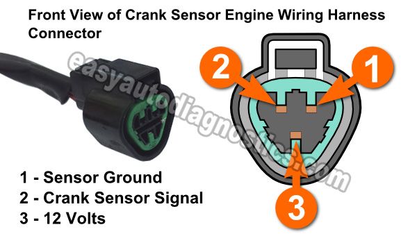
- Power Supply: One wire provides a power supply (typically 5V or 12V) from the ECU.
- Ground: One wire provides a ground connection, usually shared with other sensors.
- Signal: The third wire carries the signal back to the ECU. This signal is a digital pulse that changes state (high or low) as the teeth of the reluctor wheel pass by the sensor.
As the crankshaft rotates, the reluctor wheel passes the sensor. This disrupts the magnetic field within the sensor, causing the sensor to switch its output signal from high to low (or vice-versa). The ECU reads this signal and uses the frequency and pattern of the pulses to determine the crankshaft's position and speed.
Real-World Use: Basic Troubleshooting Tips
Let's say your engine won't start, and you suspect the CKP sensor. Here's how you can use the wiring diagram to troubleshoot the problem:
- Visual Inspection: Check the connector for damage, corrosion, or loose wires. Make sure the connector is securely attached to the sensor.
- Voltage Check: Use a multimeter to check for voltage at the power wire (with the ignition on). If no voltage, trace the wire back to the power source, checking for breaks or shorts along the way.
- Ground Check: Use a multimeter to check for continuity between the ground wire and the chassis ground. If no continuity, trace the ground wire back to the ground point, checking for breaks or corrosion.
- Signal Check: Use an oscilloscope (ideally) or a multimeter (for a basic check) to verify the signal from the sensor.
- Hall-Effect Sensor: Look for a switching signal (high/low) as the engine is cranked.
- VR Sensor: Look for an AC voltage signal that increases with engine speed.
- Continuity Check: With the sensor disconnected and the ignition OFF, use a multimeter to check the continuity of the signal wire from the sensor connector to the ECU connector. This verifies the integrity of the wire and that there are no breaks or shorts.
Important: Always refer to the vehicle's service manual for specific testing procedures and specifications.
Safety Precautions
Working with electrical systems can be dangerous. Here are some crucial safety precautions:
- Disconnect the Battery: Always disconnect the negative battery cable before working on electrical components. This prevents accidental shorts and electrical shock.
- Use Proper Tools: Use insulated tools to prevent electrical shock.
- Work in a Well-Ventilated Area: Avoid working in enclosed spaces where flammable gases may be present.
- Be Aware of Airbag Systems: Some wiring harnesses may contain airbag system wiring. Avoid tampering with these wires, as accidental deployment can cause serious injury. Always consult the service manual before working near airbag components.
- High Voltage Components: Do NOT probe ignition coils or wires unless you are trained and qualified to do so. Voltages can be lethal.
Remember, if you're uncomfortable working on electrical systems, consult a qualified mechanic.
Download the Diagram!
To help you further, we've prepared a downloadable 3-wire CKP sensor wiring diagram. This diagram provides a visual representation of the circuit, including wire colors, pin locations, and component symbols. This will be a valuable resource as you troubleshoot and repair CKP sensor issues.
(Diagram download link would be inserted here.)
Understanding your CKP sensor’s wiring diagram and system puts you miles ahead of most DIYers. Use it wisely, stay safe, and get those engines running smoothly!