
Crankshaft Position Sensor Connector Wiring
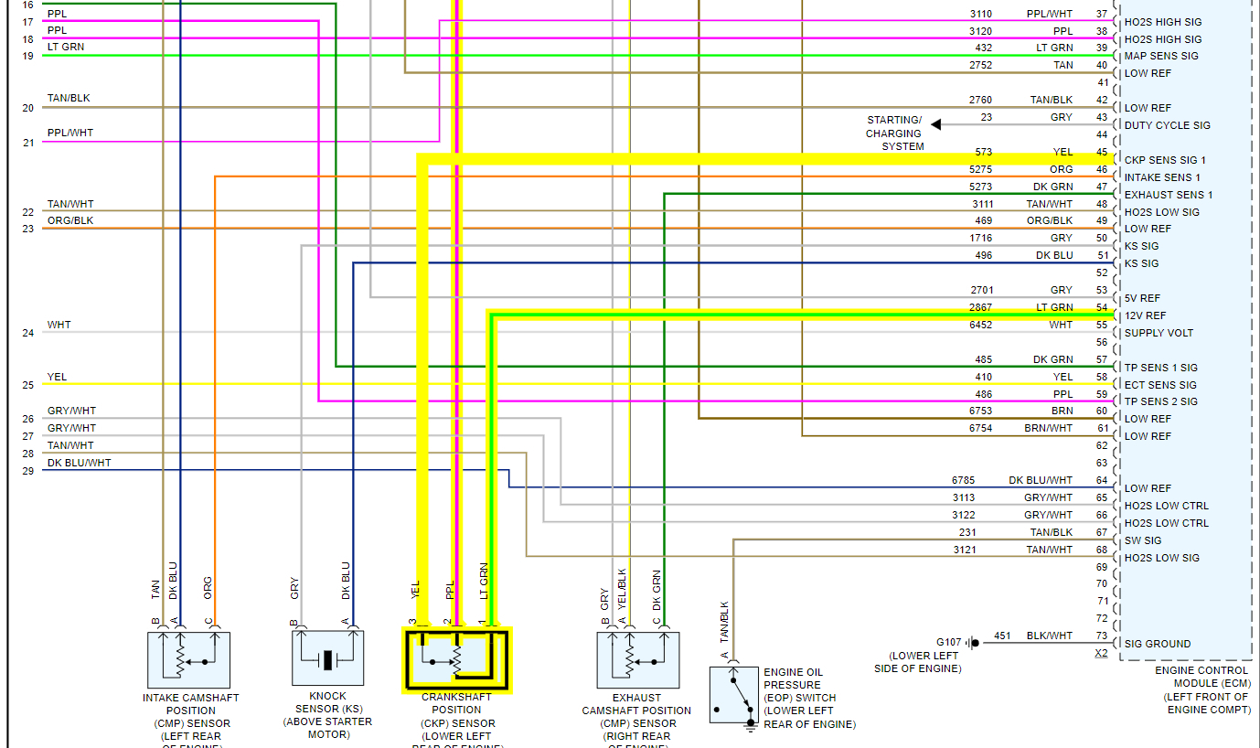
Understanding the crankshaft position sensor (CKP) connector wiring is crucial for any serious DIY mechanic or car enthusiast. Whether you're diagnosing engine problems, performing repairs, or even planning engine modifications, knowing the ins and outs of this wiring harness will save you time, money, and potential headaches. This article will provide a detailed guide to interpreting CKP sensor wiring diagrams, offering practical insights and troubleshooting tips for real-world scenarios.
Purpose of Understanding CKP Sensor Wiring
Why delve into the intricacies of CKP sensor wiring diagrams? Several key reasons make this knowledge invaluable:
- Troubleshooting Engine Problems: The CKP sensor is a vital component for engine timing and fuel injection. A faulty sensor or wiring can cause various issues, including engine misfires, stalling, and a no-start condition. Understanding the wiring diagram allows you to pinpoint the problem to a specific wire, connector, or the sensor itself.
- Performing Repairs: Damaged wiring harnesses are common, especially in older vehicles. Knowing the correct wire assignments enables you to repair or replace damaged connectors and wiring sections accurately, ensuring proper sensor function.
- Engine Swaps and Modifications: When performing engine swaps or modifications, you may need to adapt the CKP sensor wiring to the new engine management system. A wiring diagram is essential for making the correct connections.
- Learning and Diagnosis: Even if you're not facing immediate issues, understanding the CKP sensor wiring diagram expands your automotive knowledge and allows you to better diagnose potential problems in the future.
Key Specs and Main Parts
Before diving into the wiring diagram, let's familiarize ourselves with the key specifications and components involved in a typical CKP sensor circuit:
CKP Sensor Types
There are primarily two types of CKP sensors:
- Hall Effect Sensors: These sensors use a magnetic field and a semiconductor to generate a digital signal. They typically have three wires: power, ground, and signal.
- Variable Reluctance Sensors (Magnetic Pickup): These sensors generate an analog signal based on the movement of a toothed wheel past the sensor. They usually have two wires.
Connector Configurations
CKP sensor connectors typically have 2 or 3 pins, depending on the sensor type. The connector housing is designed to securely attach to the sensor and provide a weather-tight seal.
Wiring Specifications
Wire gauge and color coding can vary depending on the vehicle manufacturer. However, some common colors include:
- Power: Often red or brown.
- Ground: Typically black or brown.
- Signal: Usually green, blue, or yellow.
Refer to the specific wiring diagram for your vehicle to determine the correct wire colors and gauge.
Typical CKP Sensor Circuit Components
A CKP sensor circuit generally includes these components:
- CKP Sensor: The sensor itself, mounted near the crankshaft.
- Connector: The electrical connector that attaches the sensor to the wiring harness.
- Wiring Harness: The bundle of wires that connects the sensor to the engine control unit (ECU).
- ECU (Engine Control Unit): The computer that receives the signal from the CKP sensor and uses it to control engine timing and fuel injection.
- Relays & Fuses: These protect the circuit and other components.
Understanding CKP Sensor Wiring Diagram Symbols
A wiring diagram is a schematic representation of the electrical circuit. To decipher it, you need to understand the common symbols used:
- Lines: Solid lines represent wires. Dashed lines may indicate shielded cables or connections to ground. The thickness of the line does not usually represent wire gauge.
- Circles: Circles often represent connectors or terminal points.
- Squares/Rectangles: These typically represent electrical components like relays, fuses, and the ECU.
- Ground Symbol: A series of horizontal lines decreasing in length indicates a ground connection.
- Voltage Source Symbol: A line with a plus sign (+) indicates a positive voltage source (e.g., battery voltage).
- Color Codes: Wiring diagrams use abbreviations to represent wire colors. Common abbreviations include:
- BK: Black
- RD: Red
- BL: Blue
- GN: Green
- YW: Yellow
- BR: Brown
- WH: White
Always refer to the legend on the specific wiring diagram you are using to understand the exact meaning of each symbol.
How It Works: From Sensor to ECU
The CKP sensor plays a critical role in engine management. Here's how it works:
- Crankshaft Rotation: As the crankshaft rotates, a toothed wheel (reluctor ring) mounted on the crankshaft passes by the CKP sensor.
- Signal Generation:
- Hall Effect Sensor: The toothed wheel disrupts the magnetic field, causing the sensor to generate a digital pulse (on/off signal).
- Variable Reluctance Sensor: The movement of the teeth past the sensor induces a voltage in the sensor coil, generating an analog signal (sine wave).
- Signal Transmission: The sensor sends the signal through its wiring to the ECU.
- ECU Processing: The ECU interprets the CKP sensor signal to determine the crankshaft position and engine speed (RPM).
- Timing Control: Based on this information, the ECU precisely controls the timing of fuel injection and ignition, ensuring optimal engine performance.
Real-World Use: Basic Troubleshooting Tips
If you suspect a problem with your CKP sensor or its wiring, here are some basic troubleshooting steps:
- Visual Inspection: Carefully inspect the CKP sensor connector and wiring for any signs of damage, such as broken wires, corroded terminals, or loose connections.
- Continuity Test: Use a multimeter to check the continuity of the wires between the CKP sensor connector and the ECU connector. A lack of continuity indicates a broken wire.
- Voltage Test: Verify that the CKP sensor is receiving the correct voltage (typically 5V or 12V) from the ECU.
- Signal Test: Use an oscilloscope or a multimeter (set to AC voltage) to check the signal output of the CKP sensor while the engine is cranking. A missing or erratic signal indicates a faulty sensor.
- OBD-II Codes: Use an OBD-II scanner to check for any diagnostic trouble codes (DTCs) related to the CKP sensor. Common codes include P0335, P0336, P0337, and P0338.
Important: Always refer to the vehicle's service manual for specific troubleshooting procedures and test values.
Safety Considerations
Working with electrical systems can be dangerous. Always take the following precautions:
- Disconnect the Battery: Before working on any electrical components, disconnect the negative terminal of the battery to prevent short circuits and electrical shock.
- Use Proper Tools: Use insulated tools designed for automotive electrical work.
- Avoid Working in Wet Conditions: Never work on electrical systems in wet or damp environments.
- Handle Connectors Carefully: Avoid pulling on wires when disconnecting connectors. Use a small screwdriver or pick to release the locking tabs.
- High-Voltage Components: Be extremely cautious around the ignition system, as it generates high voltage. The coil packs, spark plug wires and the ECU connector can hold a dangerous amount of energy even with the engine off. Ensure the system is fully discharged before touching any components.
Conclusion
Understanding the CKP sensor connector wiring diagram is a valuable skill for any automotive enthusiast. By mastering the concepts outlined in this article, you'll be well-equipped to diagnose and repair CKP sensor-related issues, perform engine modifications, and expand your overall automotive knowledge. Remember to always consult the specific wiring diagram for your vehicle and follow proper safety precautions.
We have prepared a sample CKP sensor wiring diagram file for you to download. This file illustrates the key concepts discussed in this article and provides a visual reference for understanding CKP sensor wiring schematics. You can access the download link below:
Download: CKP Sensor Wiring Diagram (Sample)
By using the information, tools and a can-do attitude, you'll become an expert in this crucial area of automotive repair.