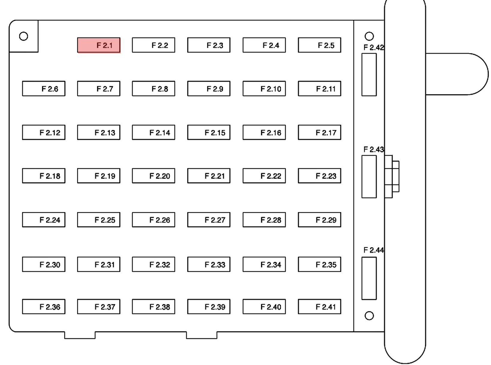
Dash 04 Mustang 2004 Ford Mustang Fuse Box Diagram
Alright, let's dive into the fuse box diagram for your 2004 Ford Mustang. This is a critical piece of documentation for any DIY mechanic or Mustang enthusiast. Whether you're troubleshooting electrical issues, installing aftermarket accessories, or just trying to understand your car's electrical system better, knowing how to read and interpret this diagram is invaluable.
Purpose and Importance
The fuse box diagram isn't just a pretty picture; it's your roadmap to understanding and fixing electrical problems. Here's why it's so important:
- Troubleshooting: When a component stops working (headlights, radio, power windows, etc.), the first place to check is the fuse box. The diagram tells you which fuse controls that circuit.
- Preventing Damage: Replacing a blown fuse with one of the correct amperage is crucial. Using the wrong fuse can cause serious damage to your electrical system and even lead to a fire.
- Adding Accessories: If you're installing aftermarket accessories like a new stereo, amplifier, or auxiliary lights, you'll need to tap into the existing electrical system. The diagram helps you identify appropriate power sources.
- Learning the System: Even if you don't have a specific problem, studying the fuse box diagram will give you a better understanding of how your Mustang's electrical system is laid out.
Key Specs and Main Parts of the Fuse Box
Your 2004 Mustang has two primary fuse boxes:
- Under-Hood Fuse Box: Located in the engine compartment, this box houses fuses and relays for high-current components like the starter motor, alternator, cooling fan, and various engine control systems. It’s generally the larger of the two.
- Interior Fuse Box: Typically found under the dashboard, usually on the driver's side, this box protects circuits for interior components like the radio, power windows, lights, and instrument cluster.
Key components within the fuse boxes include:
- Fuses: These are the sacrificial elements designed to protect circuits from overcurrent. They consist of a thin strip of metal that melts and breaks the circuit if the current exceeds a certain limit. Fuse ratings are measured in amperes (amps or A).
- Relays: Relays are electromechanical switches that allow a low-current circuit to control a high-current circuit. They're used for components that draw a lot of power, like headlights and fuel pumps.
- Circuit Breakers: Some circuits may be protected by circuit breakers instead of fuses. Circuit breakers are reusable and will automatically trip (open the circuit) when an overcurrent condition is detected. They can be reset manually.
Understanding the Symbols, Lines, Colors, and Icons
A fuse box diagram isn't just a list of fuses; it's a symbolic representation of the electrical circuits. Here's how to decipher it:
- Lines: Lines on the diagram represent wiring. Thicker lines usually indicate higher current-carrying capacity. Dotted lines might indicate shielded or grounded wires.
- Colors: Wire colors are often indicated in the diagram. These colors are standardized and can help you trace wires within the harness. Common colors include red (power), black (ground), and various other colors for specific circuits.
- Icons: Icons represent specific components. For example, a lightbulb icon indicates a lighting circuit, a fan icon indicates a cooling fan circuit, and a radio icon indicates the audio system. These icons provide a quick visual reference.
- Fuse Numbers: Each fuse is assigned a number, which corresponds to a listing in the diagram. This listing will tell you the amperage rating of the fuse and the components it protects.
- Amperage Ratings: The amperage rating (e.g., 10A, 20A, 30A) is crucial. Always replace a blown fuse with one of the *same* amperage rating. Using a higher amperage fuse can overload the circuit and cause a fire. Using a lower amperage fuse will likely blow prematurely.
Diagrams also often use standardized symbols to represent electrical components. Learn to recognize basic symbols such as resistors (zig-zag line), capacitors (two parallel lines), and diodes (triangle pointing to a vertical line).
How It Works: A Simplified Explanation
The fuse box is the central distribution point for electrical power in your Mustang. Power from the battery flows through the main power cable to the fuse box. Inside the fuse box, the power is distributed to various circuits, each protected by a fuse. When a component is turned on (e.g., headlights), electricity flows from the fuse box through the wiring to the component and back to the ground, completing the circuit.
If there's a short circuit (an unintended path for electricity with low resistance), the current will increase dramatically. This overcurrent condition will cause the fuse to blow, interrupting the circuit and preventing damage to the wiring and components.
Real-World Use: Basic Troubleshooting Tips
Here’s how to use the fuse box diagram to troubleshoot common electrical problems:
- Identify the Problem: Determine which component is not working. For example, "My headlights don't turn on."
- Consult the Diagram: Locate the fuse box diagram (we have the file available for download!). Find the fuse that controls the headlights.
- Inspect the Fuse: Remove the fuse using a fuse puller (a small plastic tool designed to grip and remove fuses). Inspect the fuse. If the thin metal strip inside the fuse is broken, the fuse is blown.
- Replace the Fuse: Replace the blown fuse with a new fuse of the *same* amperage rating.
- Test the Component: Turn on the headlights to see if they now work.
- If the Fuse Blows Again: If the new fuse blows immediately, there's likely a short circuit in the wiring or the component itself. Further diagnosis is required. Don't keep replacing fuses without finding the underlying cause.
Important Tools: A multimeter is essential for electrical troubleshooting. You can use it to check for voltage, continuity (whether a circuit is complete), and resistance. A fuse puller is also very helpful for removing fuses without damaging them.
Safety First: Risky Components and Precautions
Working with electrical systems can be dangerous. Here are some safety precautions:
- Disconnect the Battery: Before working on the electrical system, disconnect the negative battery cable. This will prevent accidental shorts and shocks.
- Never Bypass a Fuse: Never replace a fuse with a piece of wire or any other conductive material. This is extremely dangerous and can cause a fire.
- Be Careful with High-Current Circuits: Circuits that handle high current, such as the starter motor and alternator, can be particularly dangerous. Avoid touching bare wires or terminals in these circuits.
- Work in a Well-Lit Area: Make sure you have adequate lighting to see what you're doing.
- If in Doubt, Seek Professional Help: If you're not comfortable working on electrical systems, take your Mustang to a qualified mechanic.
Specific high-risk components often protected in the under-hood fuse box include:
- Fuel Pump Relay: Mishandling can lead to fuel leaks and potential fire hazards.
- Ignition System Components: High voltage circuits that can deliver a nasty shock.
- Airbag System Fuses: Tampering can cause accidental deployment, leading to injury. Always consult a professional if working near airbag systems.
By understanding your 2004 Mustang's fuse box diagram, you can confidently diagnose and repair electrical issues, add aftermarket accessories, and gain a deeper understanding of your car's electrical system. Remember to always prioritize safety and use the correct tools and procedures. Happy wrenching!
As mentioned earlier, we have the complete fuse box diagram file for your 2004 Ford Mustang available for download. This will be a valuable resource for your future electrical projects and troubleshooting needs. It includes detailed information about each fuse and relay location, as well as the amperage ratings and circuit descriptions.